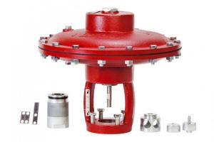
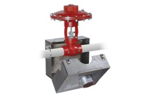
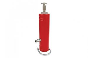

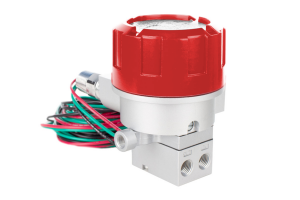
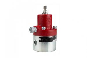
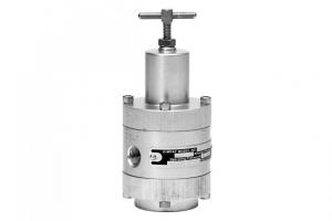
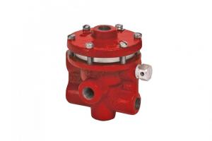
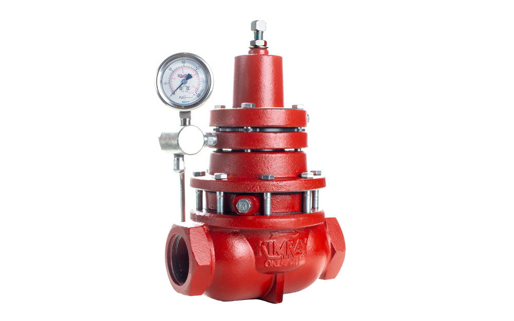
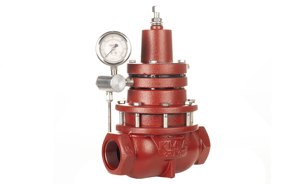
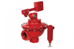
The Kimray Spring-Loaded Adjustable Back Pressure Regulator is a dependable, easy-to-operate solution for holding back pressure on an oil and gas vessel.
The primary reason a producer would want to use the spring-loaded back pressure regulator over a pilot-operated regulator is that it requires no instrument gas. This means the valve releases no emissions.
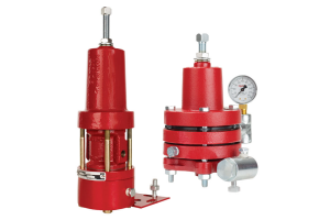
Another advantage is you can flow liquid or gas or both simultaneously. For example, in a two-phase free water knockout, it can regulate the oil and gas together, allowing the vessel to separate the water from these elements.
In this video and article, we'll show you how to repair it.
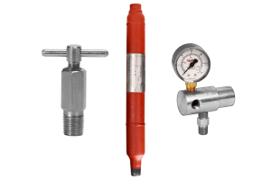
Parts & tools for Standard Spring-Loaded Back Pressure REgulator repair

- 9/16” wrench / socket
- Adjustable wrench
- Multi-purpose lubricant/grease
- Pick
- Flathead screwdriver (if lower housing does not remove easily)
- Removable Seat Tool (if damaged)
- Stem Guide (1852)
- Kimray Repair Kit (RTB1; check here for your specific model)
- Any kind of light gravity motor oil (not needed for non-lube version)
Disassembly
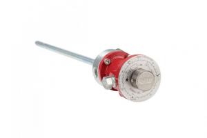
- Start by unthreading the adjustment screw to relieve spring tension.
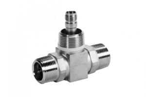
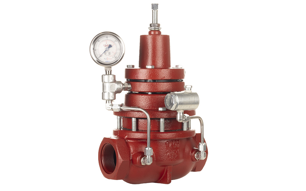
- Your model may have tubing connectors, depending on a few variables. Use a 9/16” wrench to loosen them if needed.
- Remove the bonnet bolts with a 9/16” socket wrench.
- Remove the bonnet, upper spring plate guide, inner and outer spring, and lower spring guide.
- Next, remove the lower housing. If it’s stuck from rust or corrosion, use a flathead screwdriver to separate them.
- Appropriately discard the oil from the lower housing.
- Remove and discard the gasket from the body. Depending on the condition, you may need to scrape off some of the old gasket which may be stuck to the body.
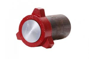
- Inspect the removable seat for damage. You’ll only want to remove the seat if there are signs of corrosion, pitting or scoring. If you do not have the correct tool, you may end up doing more damage to the seat trying to pry it out. This part is also not included in the repair kit and will need to be ordered separately if you need to replace it.

- Remove the valve body from the vise and put in the lower housing assembly. Secure it by the flats of the nut and NOT the ratio plug.
- Unthread the assembly with a 9/16” wrench.
- You can discard the nut, there is a replacement in the repair kit.
- Remove the diaphragm plate and discard the diaphragm.
- Remove the lower diaphragm plate from the stem.
- Lift off the lower housing and then remove the assembly from the vise.
- Stainless steel internals can be used when this valve is subject to corrosive applications. These internals include the stem, ratio plug, diaphragm plate, removable seat and the seat disc.
- Using copper vise jaw plate covers to avoid damage, put the stem into the vise, then remove and discard the nut with a 9/16” wrench.
- Remove the seat disc with the soft seat and ratio plug.
- Discard the soft seat.
- Place the seat disc back on the stem, followed by the new soft seat, then ratio plug.
- Add grease to the stem threads, then tighten the new nut in place.
- Using a pick, remove and discard the two backups and the quad ring from the lower housing.
- Stretch the backup slightly to make it look like a spring. Insert one end of the backup into the lower housing and use a pick to rotate it in a counterclockwise motion until it’s fully installed.
- Next install the quad ring. Pinch and fold it to make it easier to install in the lower housing.
- Push the quad ring and first backup all the way down to the bottom of the lower housing channel to make room for the last backup.
- Again, stretch it out, then insert it into the lower housing and rotate counterclockwise.
- Add grease to the backups and quad ring.
- Remove the stem from the vise and secure it by the nut on the opposite side.
- Next, we’ll install the stem into the lower housing. It's a good idea to use a Kimray stem guide to avoid sheering your quad ring.
- Place the lower diaphragm plate on the stem, textured side up, followed by the new diaphragm from the repair kit, bevel side down.
- Next, replace the diaphragm plate. Grease the stem threads and tighten with the new diaphragm nut.
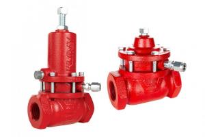
NON-LUBE model VARIATION
If you are repairing a non-lube model, the lower housing will look a little different and there will be a few other pieces in the repair kit.
The non-lube option is offered for many regulators and low pressure control valves. It is commonly used in applications where the orientation of the piping is vertical making it difficult for the oil to communicate with the stem. It could also be used in cases where the process media does not allow for potential contaminants, such as oil lubricant.

- After you’ve removed the stem assembly from the lower housing, use an adjustable wrench to remove the stem seal retainer. You can discard the retainer and washer along with all the O-rings and backups.
- To replace these components from the repair kit, start with placing the new washer in the lower housing.
- Install the O-ring on the retainer and then apply grease.
- Put the O-ring onto the channel seal.
- Then assemble the packing inside the retainer with a backup, O-ring and second backup.
- Thread the retainer onto the lower housing. Because the packing is loose, it may need to be realigned before you tighten the retainer fully.
How to Assemble the Spring-Loaded Back Pressure Regulator
- Clean any debris from inside the body and the surface where the gasket will set.
- If you are replacing the removable seat, put the new gasket on the seat and then apply grease.
- Install the removable seat into the body with the Kimray Seat Removal Tool. Be careful not to overtighten the seat and damage the gasket.
- Apply grease to the gasket surface of the lower housing. Put on the gasket, then grease the top of the gasket.
- Replace the lower housing assembly on the valve body.
- Fill the lower housing with any kind of light gravity motor oil until the communication hole to the lower stem is fully submerged. When you cannot see the communication hole, adding more oil is a better practice than not adding enough. (If you’re using the non-lube version, no oil is necessary.)
- Replace the lower spring guide, springs, and upper spring guide. Add grease to the upper spring guide if necessary.
- Replace the bonnet and hand start your bolts to avoid cross threading. Tighten the bolts in a star pattern to complete the repair.
