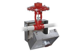
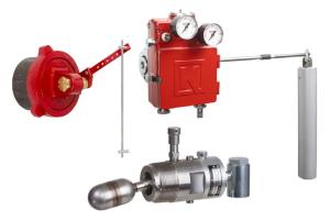
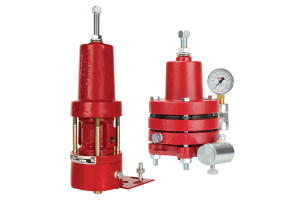
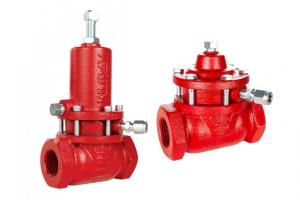
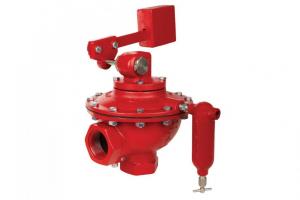
The Electric Valve Controller package is a compact, easy-to-use solution for oil and gas automation, including remote monitoring and control of your production.
In this video and article, we'll show you have to assemble an Electric Valve Controller package. This placement of components will provide the smallest footprint and the most efficient use of tubing.
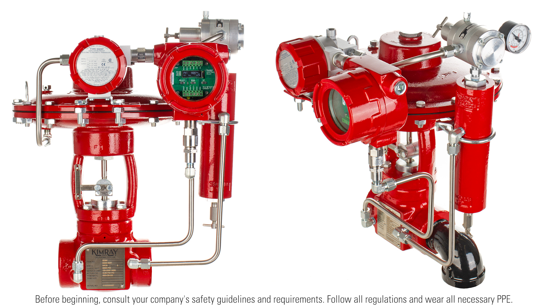
Before you get started, you’ll want to put on your appropriate PPE and be sure to follow all your company’s safety requirements.
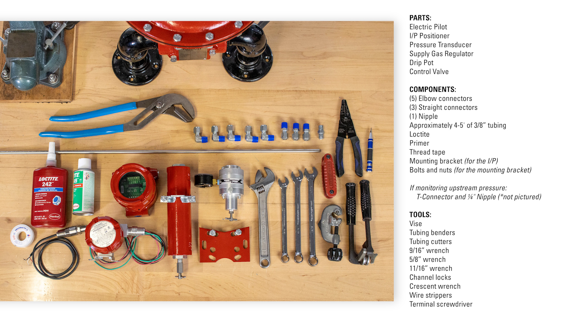
Parts:
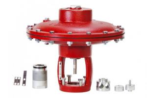
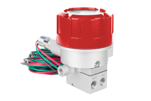
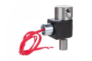
- Electric Pilot
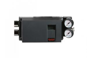
- I/P Positioner
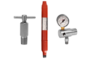
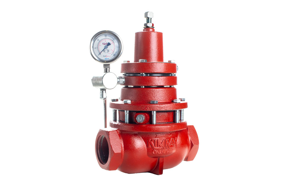
- Pressure Transducer
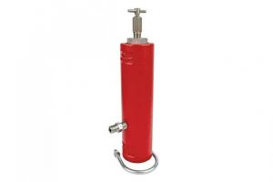
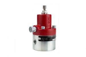
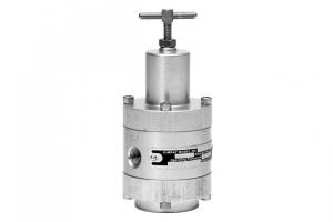
- Supply Gas Regulator
- Drip Pot
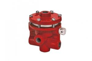
- Control Valve
Components:
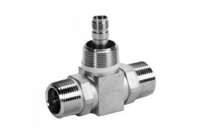
- Connectors:
- (5) elbow connectors
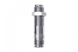
- (3) straight connectors
- (1) nipple connector
- Approximately 4-5' of 3/8” tubing
- Loctite
- Primer
- Thread tape
- Mounting Bracket (for the I/P)
- Bolts and nuts (for the Mounting Bracket)
If monitoring upstream pressure:
- T-Connector
- Additional ¼" Nipple
Tools:
- A vise
- Tubing benders
- Tubing cutters
- 9/16” wrench
- 5/8” wrench
- 11/16” wrench
- Channel locks
- Crescent wrench
If doing electrical hookup:
- Wire strippers
- Terminal screwdriver
FITTINGS
First, we’ll install the fittings into each component, then mount them to the valve body.
For all tubing connections, apply primer and Loctite. For all non-pressurized, threaded connections (nipple from I/P to YEP & YEP to transducer connections), use thread tape.
- Put the I/P in a vise.
- Using a crescent wrench, mount a straight connector in the inlet side of the I/P on the same side as the wires.
- Mount another straight connector in the opposite side outlet.
- Remove the two ¼" plugs from the valve body and use them to plug the remaining open inlet and outlet of the I/P.
- Remove the I/P from the vise and insert the Supply gas regulator.
- Put a nipple in the input of the SGR and a straight connector in the output of the SGR.
- Now remove the SGR and put the drip pot in the vise.
- Thread the nipple of the SGR into the drip pot.
- Put an elbow in the inlet of the drip pot.
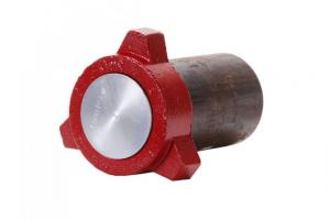
- Put the pressure transducer in the vise.
- Now, install an elbow in the inlet of the pressure transducer.
- Secure the valve. If you use a vise, mount the body so that you can still access the ports, leave room so you can install the connectors and tubing later.
- Install an elbow connector into the upstream and downstream of the valve body.
- Install an elbow connector on the underside of the valve actuator.
MOUNTING
With the fittings attached, now we’ll mount the components to the valve.
- Using 9/16” and 11/16” wrenches, bolt the bracket for the I/P to the topworks. Do not fully tighten the bolts as it will help when installing the tubing later.
- Bolt the I/P to the bracket.
- Use a 7/64” Allen wrench to remove the board of the electric pilot so you can feed the wires through.
- Now, mount the electric pilot to the I/P. Apply thread tape clockwise around the thread of the I/P nipple. (When the fitting is connected, the fitting is installed the same clockwise direction, sealing the fitting & not peeling back.)
- Then attach the pressure transducer to the bottom of the pilot.
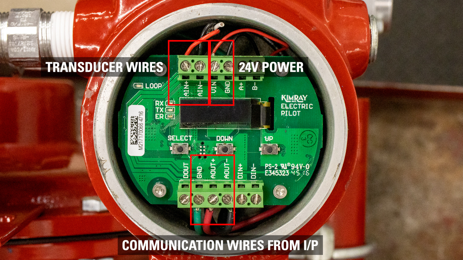
WIRING
- Next hook up the wires from the I/P to the pilot.
- Use wire strippers to remove the insulation of the wires.
- Connect the communication wires from the I/P to the analog output of the electric pilot. (AOUT+ & AOUT-)
- The analog IN (AIN+ and AIN-) is where you connect the transducer to the pilot.
- The VIN port and GRN is where you would connect 24V power to the pilot. If you’re building this package prior to installation, leave these open for now.
FINISH MOUNTING
- Now, mount the drip pot and SGR onto the valve. The output of the SGR should be pointing toward front of the valve.
TUBING
Now bend and install the tubing.
- First, connect tubing from the upstream port of the valve to the drip pot.
- Then tube downstream pressure to the pressure transducer.
- Connect tubing from the Supply Gas Regulator to the I/P.
- Tube the I/P to the valve actuator.
Tighten the bolts on the mounting bracket now that the tubing is connected.
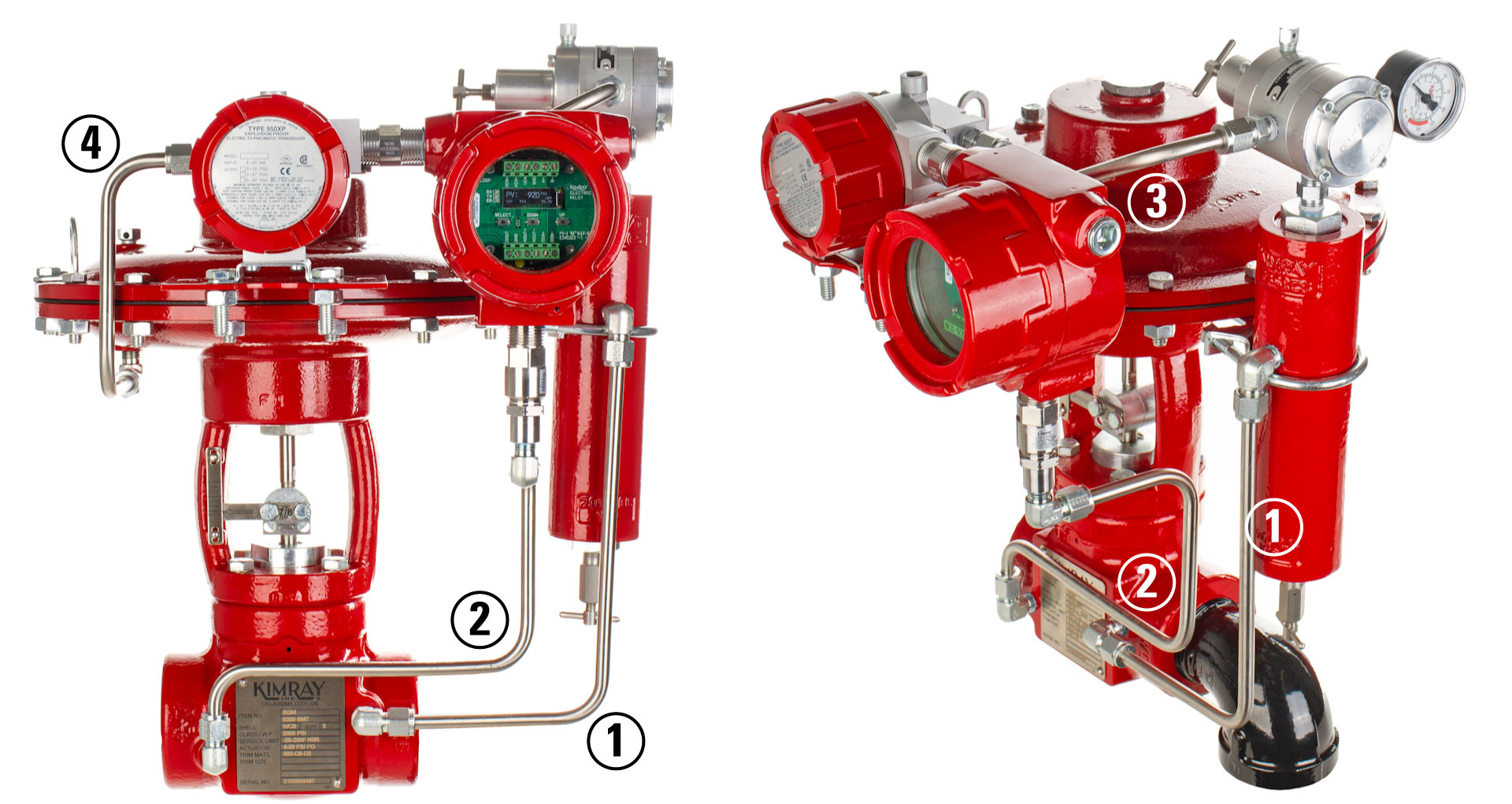
To monitor upstream pressure (for back pressure), remove the tubing to the downstream (2). Instead connect the upstream tubing (1) to the transducer by adding a ¼" nipple and T-connector to the transducer. Then tube the T-connector to the drip pot.