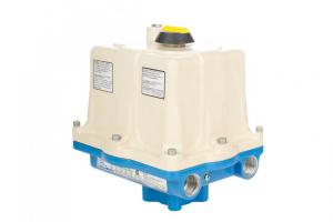


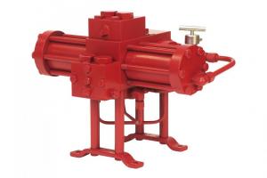
 The new Kimray Electric Actuator is helping energy producers increase efficiency, lower their emissions, and improve their operator safety.
Let's walk through the basics of calibrating for your specific control valve.
Ordering Options & Mounting
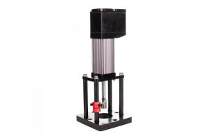
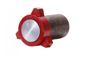
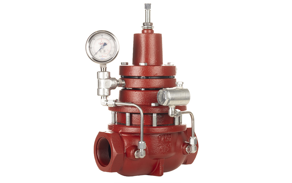
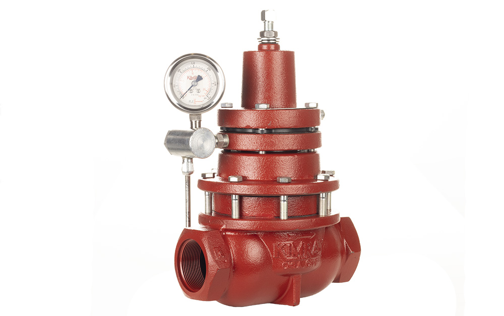
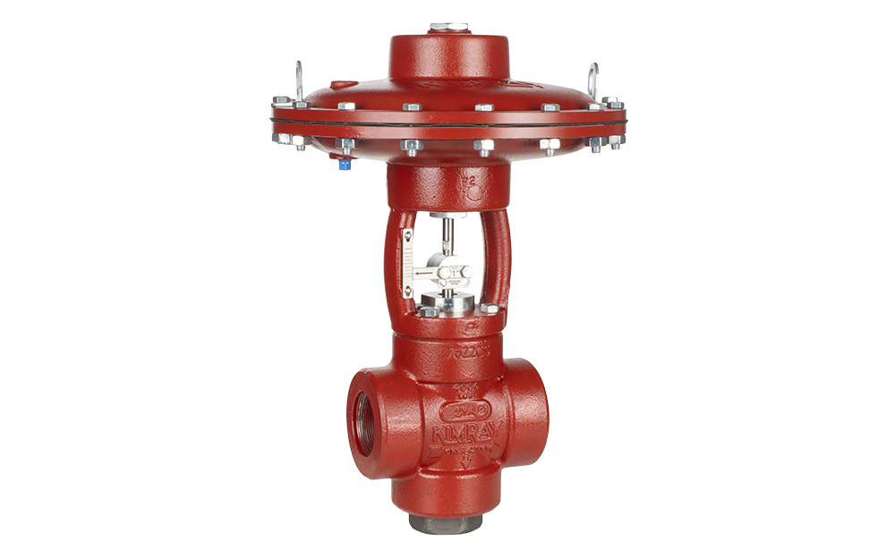
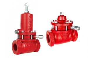
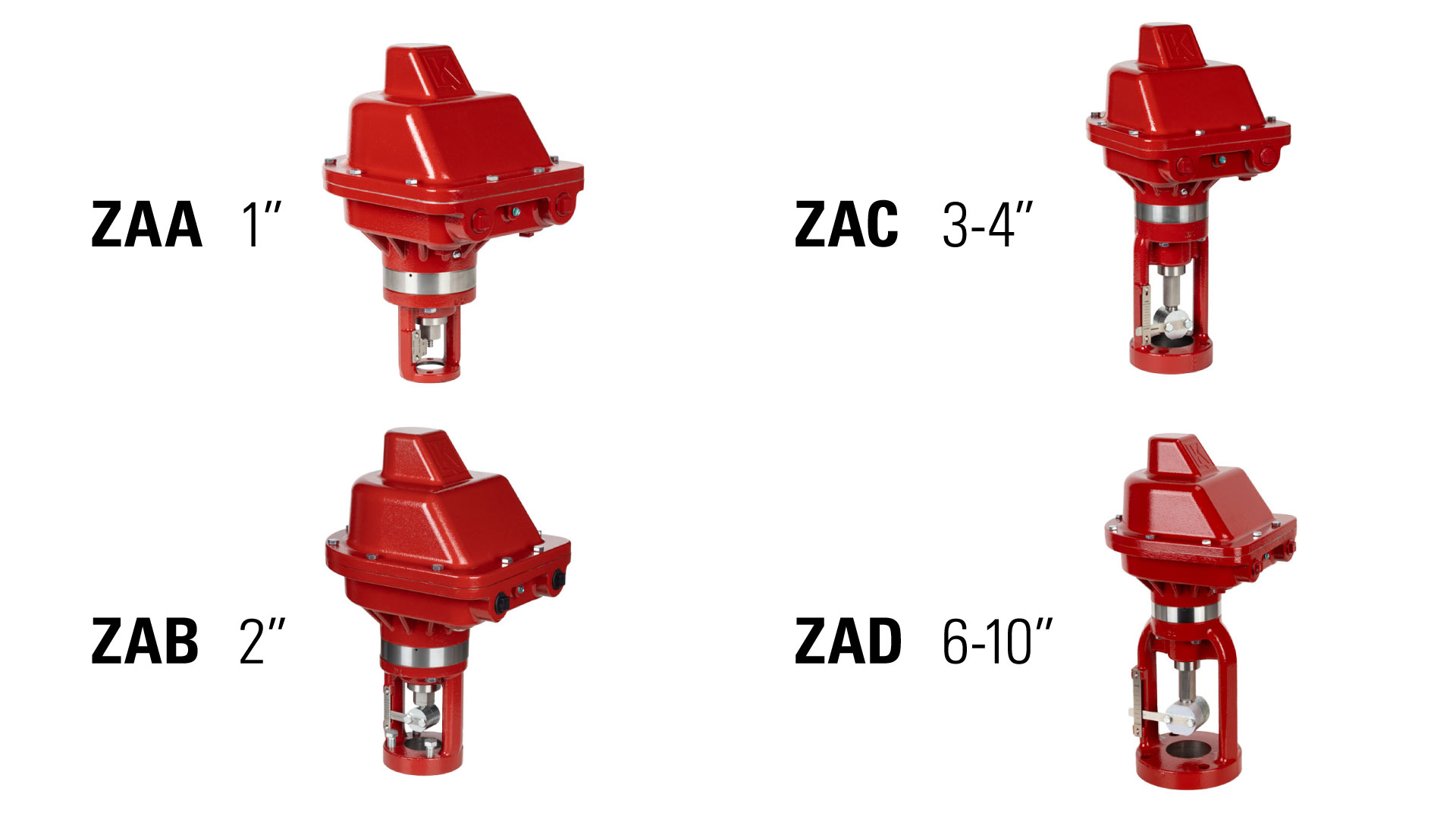
We’ve made ordering the new electric actuator very easy. There are four options to choose from based on the connection size of your valve body. The yoke with the stem and coupling block changes sizes, but everything above the silver band remains the same on all models.
- ZAA 1”
- ZAB 2”
- ZAC 3-4"
- ZAD 6-10"
To mount the actuator, simply thread the four bolts into the valve body in any direction convenient for access. If you purchase it as a control valve package it will already be mounted for you.
Connecting Outside Power Supply
First, remove the lid. On the circuit board, wire the power supply into the positive and negative voltage input, labeled VI+ and VI- on the board. This is a 12-24V DC input and requires a 10 Amp overcurrent protection device.
After the connection is complete and the power is turned on, the green LED will turn on.

Battery Backup
The actuator is equipped with a battery backup, which comes unplugged. After power is supplied to the board, you can plug in this battery.
It requires a minimum of 16 volts to charge. If you’re using 12 volts, the battery backup will not be applied.
Also note that if your wire size is incorrect, or the distance from the power source to the actuator is too long, there is potential for voltage drop issues.
Valve Calibration
It’s important to not calibrate the actuator before it has been mounted. Without a hard stop, the linear screw can go past set point and must be readjusted.
Now that you have mounted and powered it up, you're ready to calibrate it to your valve body size.
- The screen will say “Calibrate Valve.”
- You will need to press the up button.
- It will now say “Calibrate press right.”
- Press the right button, and the screen will say “Finding Open.”
- Once fully open, it will say “Parking Valve.” Then it will drive closed.
When calibration is complete, it will take you to the home screen and that’s it—35 seconds and your actuator is calibrated for a 2” valve body. This will vary by a few seconds depending on valve body sizes.
Should you ever need to recalibrate from the home screen press right until you get to Reset Menu, press down to reach Calibrate Valve, and follow the same process outlined above.
Control Input Setup (Wiring):
You can set the actuator up for discrete, analog or Modbus operation. Reverse protection is included in the hardware, so if the inputs are accidentally connected in reverse, the board won't function, but it won’t be damaged.
Discrete Operation
Discrete operation is like a light switch—it’s either on or off, or in this case, open or closed.
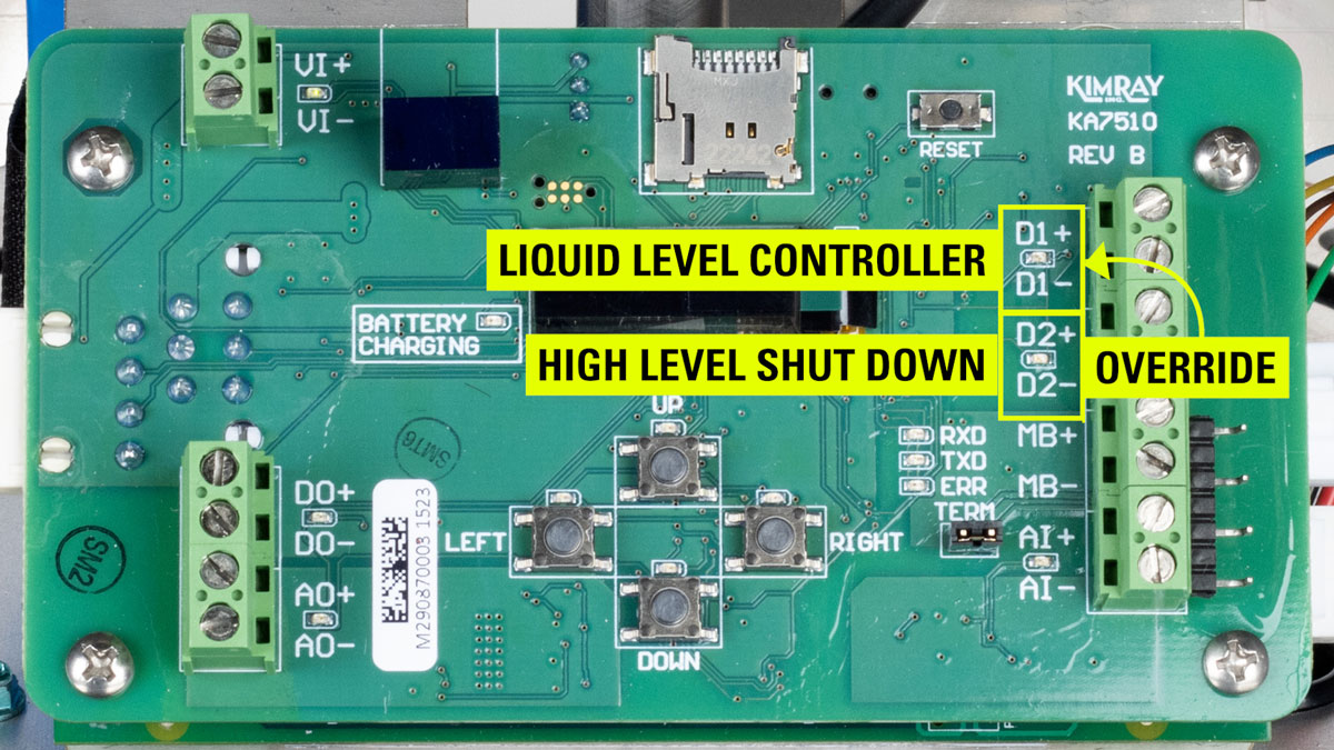
On the board you’ll see D1+, D1-, D2+, and D2-.
Out of the box, the electric actuator comes enabled with discrete 1 as your primary controller and discrete 2 as an override. What this means is that if there is a signal to discrete 2, it will prioritize that signal over discrete 1 and override what discrete 1 is communicating to it.
As an example, in an oil and gas application, discrete 1 could be used for level control in a separator, with discrete 2 as a high-level shut down. Let’s say discrete 1 is wired to an electric liquid level controller and discrete 2 is wired to a level switch above the level controller set point. If the liquid level rises to the level switch due to a malfunction of the level controller, it will override the signal coming from the level controller and shut the valve.
If that’s the type of application you want to use it for, wire the level controller in to D1+ and D1- and the level switch to D2+ and D2-. These need to be active inputs of 8-30 Volts.
You know your connection is complete when the green LED is on.
If you don’t need that override signal, you can just wire discrete 1 and it will function without a discrete 2 signal.
The power supply you are using for voltage in can also be used for your discrete signal power with the use of a jumper. When installing a jumper make sure power is disconnected from the actuator.
Discrete output
Discrete output (labeled DO+ and DO- on the board) can be used to relay the signal to a light or alarm on site.
Analog Operation
If discrete is like a light switch, think of analog operation like a dimmer—it may be partially open instead of only on or off.
When set up for analog, the actuator will be able to control span. This means that any 4-20 milliamp device will be able to control the actuator between 0-100% fully open and closed.
For example, say you want to set it up for a level controller on a separator, and you want to keep a set point where the valve doesn’t fully close or open but modulates. In this scenario, you would wire your level controller to analog positive and negative. The actuator knows what to do with that information and will act accordingly.
Analog input wires should have loop power provided by the user or the controller. Because this actuator implements an isolated 4-20 milliamp input loop, the same power supply for Voltage-In (VI+ & VI-) can provide loop power.
Analog output
Analog output (AO+ and AO-) can be used to relay the signal to a light or alarm on site.