
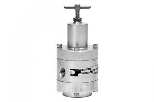
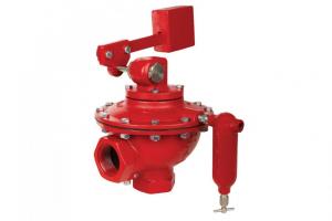
The Kimray Gen 3 Liquid Level Controller is a simple, versatile solution that delivers precise level control.
In this video, I'll show you how to easily configure, set up and operate the Gen 3. By the end of the video you'll be able to:
- switch the mount orientation
- convert between snap (discrete) and throttle (proportional) modes
- change from direct to indirect acting mode
- adjust the span and top level
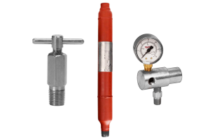
Parts Needed for Installation
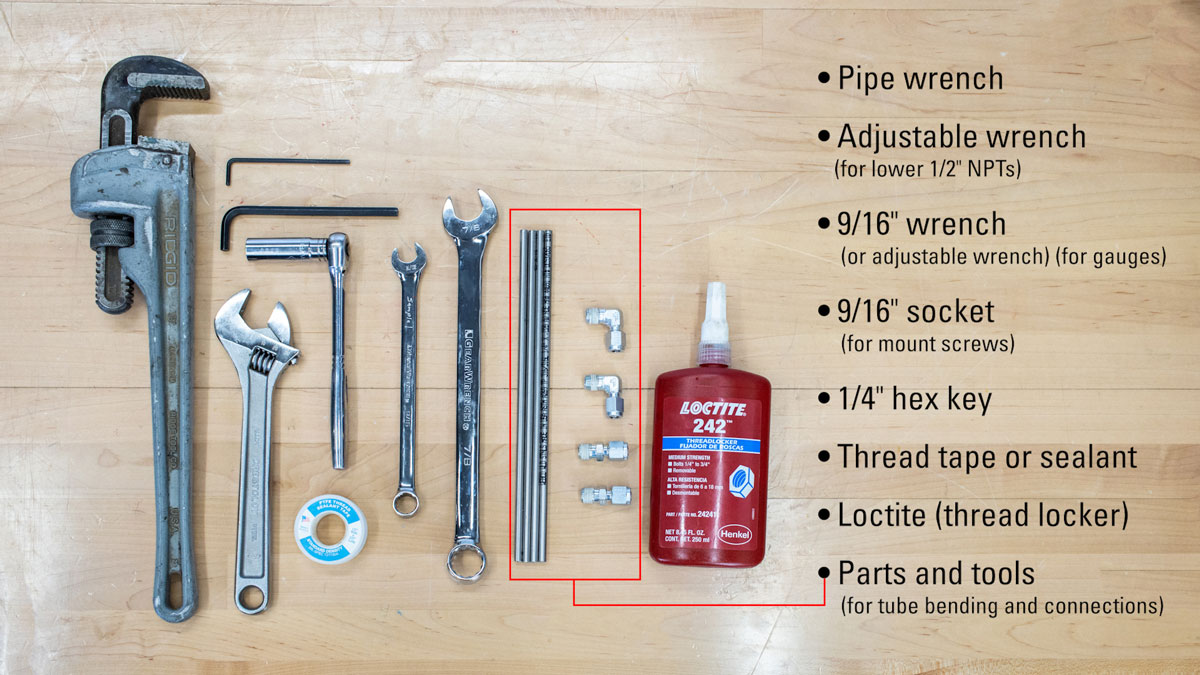
The Gen 3 includes a 1/8" hex key for the pilot and lever fasteners, and it can be conveniently stored inside the enclosure as shown in the video.
In addition to this tool, you will also need the following:
- Pipe wrench
- adjustable wrench (for lower 1/2" NPTs)
- 9/16" wrench (or adjustable wrench) (for gauges)
- 9/16" socket (for the mount screws to change orientation)
- 1/4" hex key for 1/4" NPT plugs
- Thread tape or sealant
- Loctite (thread locker)
- Any parts and tools needed for tube bending and connections
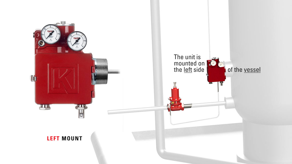
You can purchase the Gen 3 configured for either left or right mount. As a reminder, left mount means the unit is mounted on the left side of the vessel.
For back mount applications, we recommend using a left mount because of the latch location.
ORIENTATION
Left or Right Mount Conversion
- To switch between left and right mount, start by removing the spring adjustment assembly with an adjustable wrench.
- Then remove the ½" NPT plug.
- Use the included hex key to loosen the set screw at the bottom of the torque lever and slide it off the shaft.
- Remove the cap screws with a 9/16" socket and rotate the mount 180°.
- Reinstall the cap screws with thread locker (Loctite).
- Then reinstall the torque lever and tighten the set screw.
- Install the spring adjustment assembly. The Spring Adjustment Assembly always goes on the same side as the displacer.
- Install the 1/2” NPT plug on the other side.
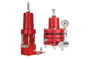
PILOT Configuration
Direct or indirect acting; Throttle or snap mode
The pilot lever should be mounted on either the left or right side depending on the operation—whether it will be operating in snap or throttle mode and whether it’s going to be direct or indirect acting.
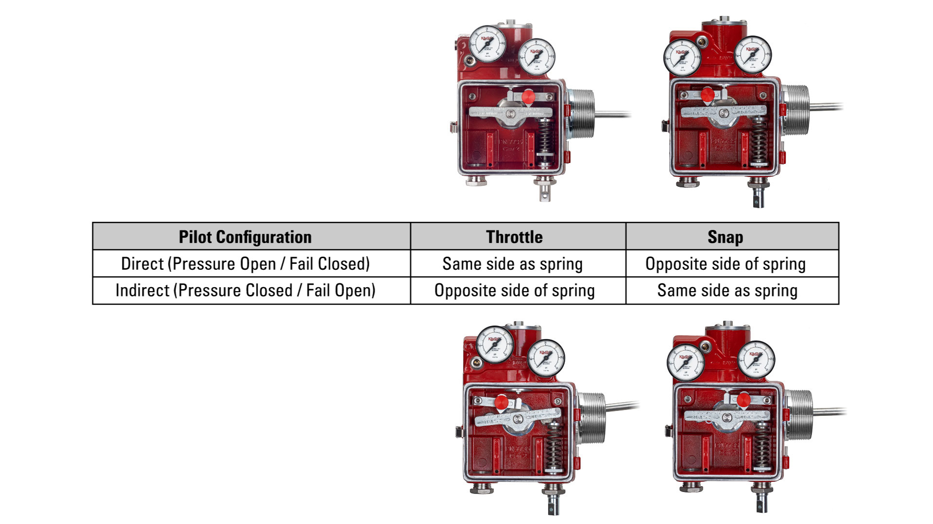
Use the table to determine which side of the unit the Pilot Lever should be on. This information is also available on the inside cover of the unit.
As an example, if the desired mode is Throttle and Direct Acting, you would want to mount the pilot lever on the same side as the spring.
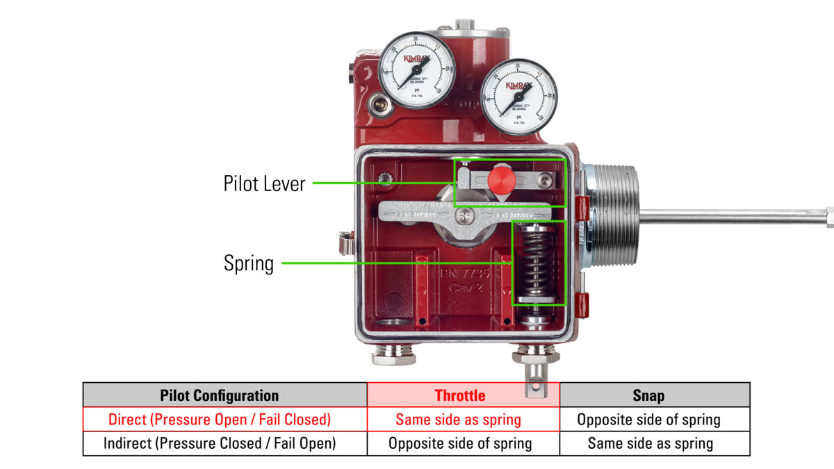
- Change the location of the pilot lever as needed by simply removing the screw, and moving the pilot lever to the other side.
- The sensitivity knob should be oriented so that it is facing outward toward the operator.
- Ensure that the protrusion is facing up, so it contacts the pilot actuator pin.
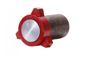
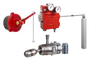
DISPLACER (Vertical / Horizontal)
The displacer can be assembled in either vertical or horizontal orientation.
- To install vertically, apply thread locker to the male threads on the displacer arm, and simply attach the displacer assembly to the displacer arm.
- For horizontal orientation, remove the rod assembly from the displacer, apply thread locker to the male threads on the arm and connect the displacer directly onto it.
INSTALLATION ONTO VESSEL
Before beginning installation, make sure all pressure is released from the vessel and confirm there is no pressure in supply gas or instrument air lines.
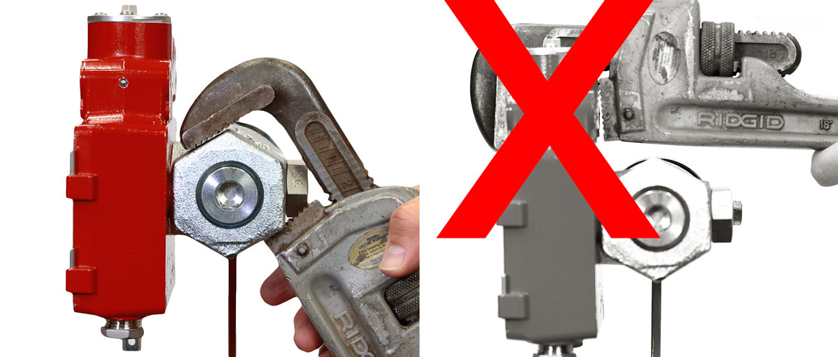
- For NPT Connections, apply thread tape or sealant to the threads of the mount. Tighten sufficiently to seal the threads using a wrench on the flats of the mounting piece.
- Do not use a wrench on the enclosure to tighten the connection.
- Orient the enclosure vertically with the pilot on top when finished.
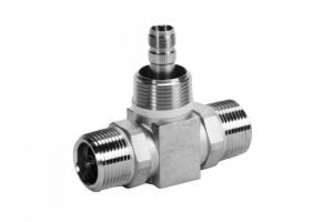
CONNECTIONS
Supply, output, and vent
Remove all plastic plugs from the ports before beginning. All the following connections and gauges must be sealed with thread tape or sealant before installation.
Throttle mode:
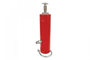
- Use any of the three ports labeled "T” to connect the supply gas filter and the supply line.
- Connect the pressure gauge to one of the remaining "T" ports.
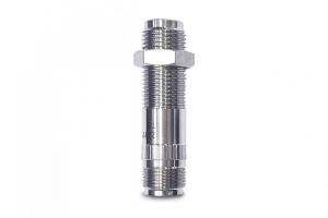
- Install a 1/4" NPT socket plug into the one remaining "T" port.
- In Throttle mode, the ports labeled "S”, should be used for vent.
- Connect the output line and pressure gauge to the two ports labeled “OUT”.
Snap mode:
- Use any of the three ports labeled "S” to connect the supply gas filter and the supply line.
- Connect the pressure gauge to one of the remaining "S” ports.
- Install a 1/4" NPT socket plug into the one remaining "S” port.
- In Snap mode, the ports labeled “T”, should be used for vent.
- Connect the output line and pressure gauge to the two ports labeled “OUT”.
Now you are ready to turn on the supply gas and calibrate the unit.
Set Point CALIBRATION
Calibrate the set point with no liquid on the displacer.
Throttle mode:
- For a fail closed (FC) Valve: With the output at 0 PSI, turn the set point adjustment knob counterclockwise to produce about 10 PSI. Then turn clockwise and stop once the output reaches 0 PSI.
- For a fail open (FO) Valve: With the output at 0 PSI, turn the set point adjustment knob clockwise until full output pressure is produced.
Snap mode:
- For a fail closed (FC) valve: With the output at 0 PSI, turn the set point adjustment knob counterclockwise to “snap on”, producing the full output pressure. Then turn the knob clockwise and stop once the output pressure reaches 0 PSI.
- For a fail open (FO) valve: At full output pressure, turn the adjustment knob counterclockwise to “snap off” where the output pressure drops to 0. Then turn the knob clockwise until full output pressure is reached.
SETTINGS & ADJUSTMENTS
Throttle mode:
- Start with the sensitivity fulcrum at the center hashmark of the pilot lever.
- If it is holding the desired span, no further adjustments are needed. If it isn’t, move the sensitivity fulcrum slightly inward or outward to get the desired span.
Snap mode:
- Start with the sensitivity fulcrum at the inward most hashmark. This should yield the smallest span.
- Adjust the fulcrum outward as needed until the desired span is reached.
To speak with an expert about your liquid level control challenges, contact your local Kimray store or authorized distributor.