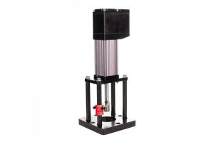
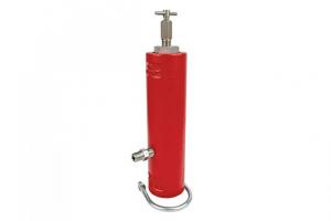
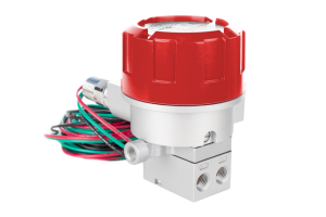
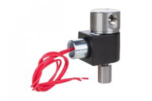
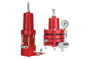
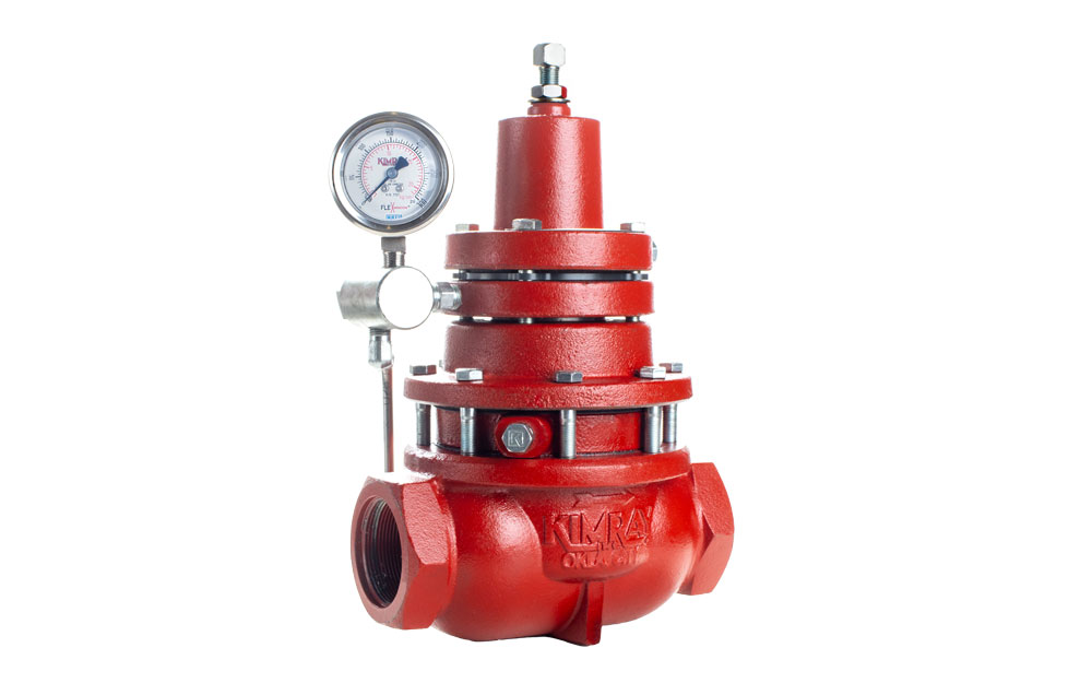
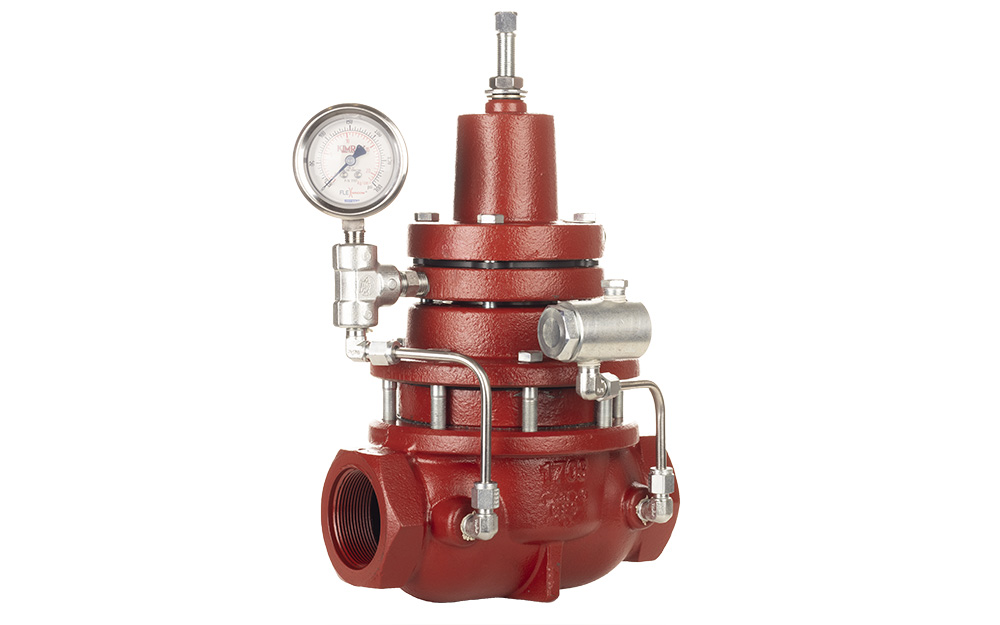
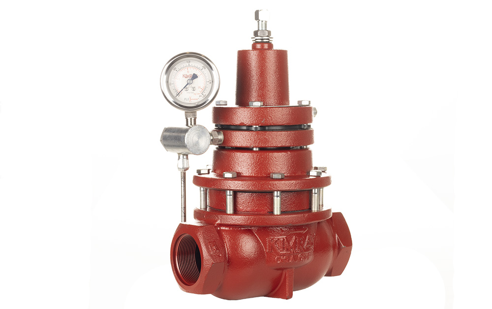
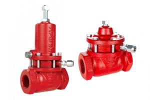
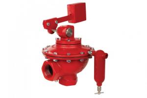
A Pneumatic Level Switch can be used as either a high-level or low-level switch in a pressurized vessel. It sends a pneumatic signal, which can be used to actuate a control valve open or closed. It can also be used in place of a level controller for on/off service in tight spaces—for instance, in a 12” diameter vertical separator.
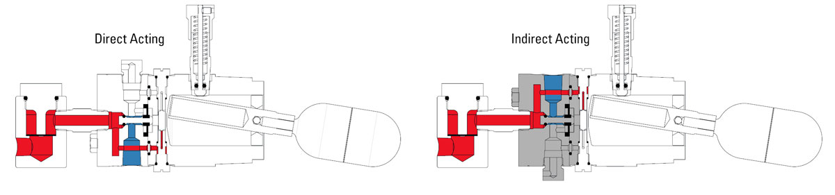
This switch is field-reversible from direct acting to indirect acting, so it can be used in conjunction with a fail-open or fail-closed control valve.
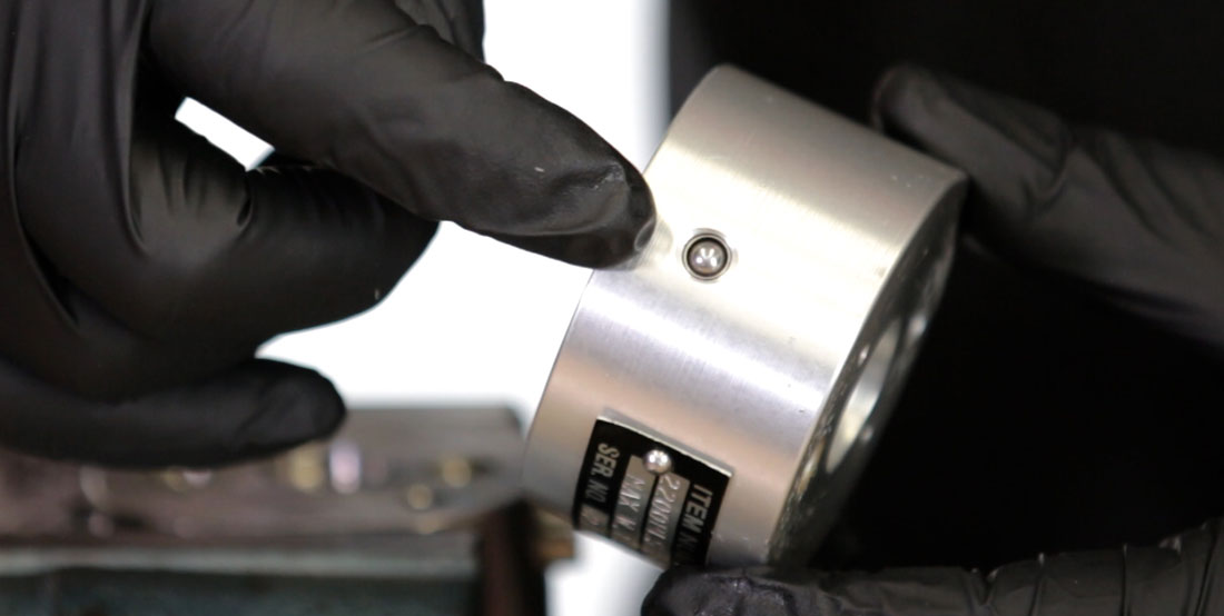
You can test the level switch by holding down the manual override. We recommend testing this at least every six months to confirm the level switch is working properly.
We also recommend using a repair kit at least once a year for preventative maintenance. While the body will last for many years, the internal components and soft goods can wear out more quickly.
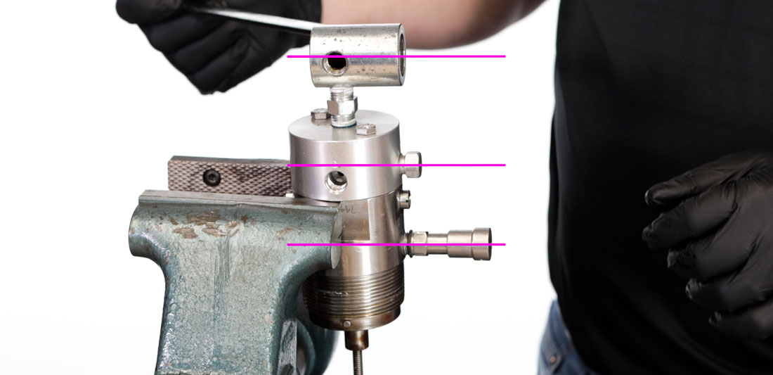
A convenient feature of the switch is that it can be repaired without being removed from the piping. In this video, we use a controlled environment and a vise.
Tools Needed

For this job, you will need the following tools, equipment and chemicals:
Tools:
- Adjustable wrench (for filter cap)
- 7/16” Socket (for pilot body bolts)
- 9/16” Wrench (for override fitting)
- 5/64” Hex wrench (for override set screw)
- Flathead screwdriver (channel locks if necessary)
- Pick
- Punch
- PPE / Nitrile gloves
Chemicals:
- Thread locker (Loctite 242) (if removing float)
- Thread sealant (Loctite 567) (for override)
- Brake parts cleaner
- Grease
- Oil
Kimray Components:
- Repair Kit: RZX
How to repair the Liquid Level Switch
Notes:
- If you are unthreading the switch from the vessel, place the switch in the vise but tighten only on the flats so that you do not damage the threads or housing.
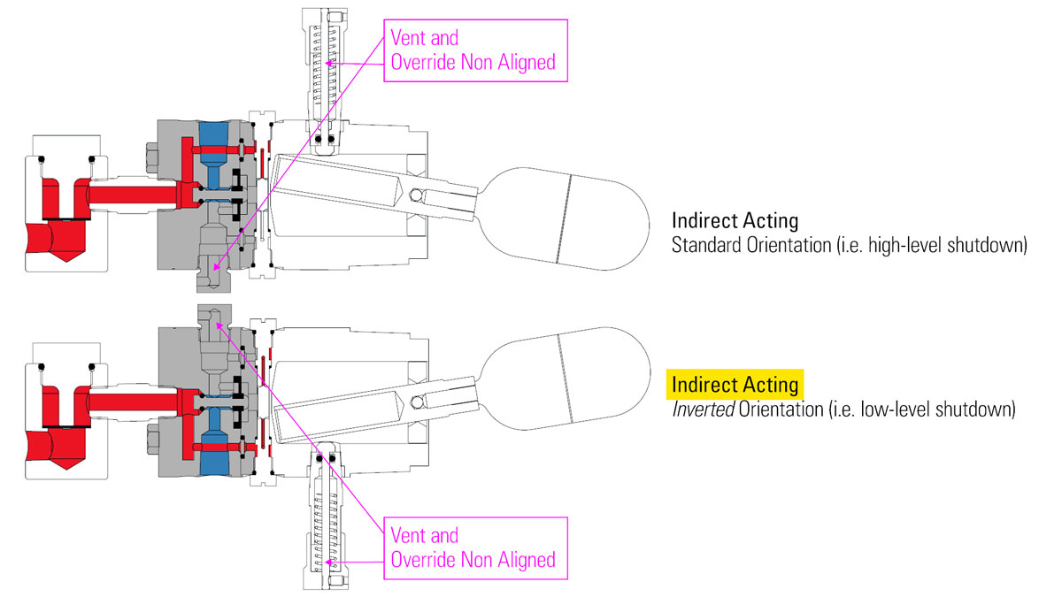
- Also note the orientation of the pilot body. If the vent is on the same side as the manual override, it is set up in direct acting mode. If you’re not changing applications, you’ll want to make sure to assemble this in the same orientation later.
Steps:
- First, remove the filter cap using an adjustable wrench.
- Use a pick to remove and discard the O-ring.
- Then discard the 6 filter screens inside the filter body.
- Remove the nipple from the body with a 5/8” wrench.
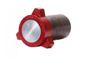
- Use a 7/16” socket to unthread the bolts in order to remove the pilot body. Note that there is a small plug on the pilot body assembly. This is an internal plug inserted during the machining process and should never be removed.
- Remove the diaphragm by using a pick to lift it. This piece will be discarded, so if you damage it during this process that’s okay. Be aware once the diaphragm is removed, the stem may fall out of the body. Keep the stem to reuse.
- Discard the O-ring from the stem, then set the stem aside.
- On the housing, remove the two (2) O-rings and two (2) disc filters. They should come out together.
- Reposition the housing in the vise so you can access one of the seats.
- Use a screwdriver to unthread the first seat. You can use channel locks to loosen the seat if it is stuck.
- Once you’ve removed the first seat, the shuttle may fall out depending on how the switch is oriented. If it hasn’t fallen out, remove it when you flip the unit around.
- With the switch secured in the vise, remove the second seat.
- Each seat has two (2) O-rings on it to discard. The bottom one may be stuck in the body, so use a straight pick to get it out.
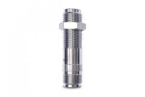
- Next, use a 9/16” wrench to loosen the override fitting.
- Use a 5/64” hex wrench to unthread the set screw and remove the cap.
- Now remove the spring and stem and set them aside.
- Remove and discard the O-ring from the threads on the override. On our level switch, the O-ring had disintegrated so there was nothing to remove.
- And lastly, use a straight pick to discard the O-ring located inside the override.
How to inspect the Liquid Level Switch
- With the level switch disassembled, next, inspect and clean each component with compressed air to make sure the body is free from contaminants. If you use brake cleaner, wipe it clean before assembly.
- Clear the vent plugs of any debris.
- Inspect the float for any punctures or damage.
Float/Float Arm Disassembly
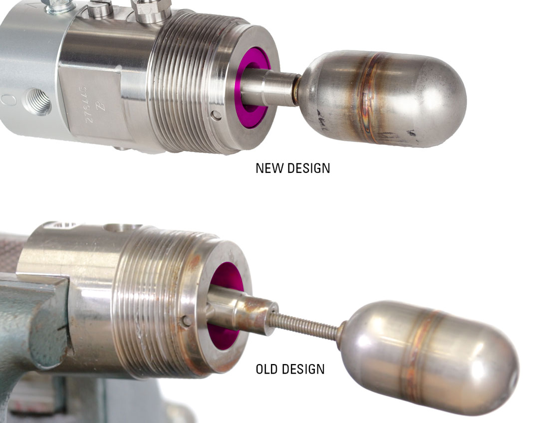
You may need to inspect the float lever more closely or clean any solid buildup inside the level switch. This model (used in the video) was manufactured in 2013 and has more space for debris to accumulate. Newer models have a plug in this area, but the removal of the float is the same.
- Start by loosening the set screw and/or the float extension. This will allow you to then slide the pivot pin out with a punch. Clean out any solids, inspect the components for any damage, then reinstall it.
- If you have removed the float, use primer and Loctite when you reattach it on the threads.
- At this point, you can clean up your station, open your repair kit and begin assembly.

How to Assemble the Liquid Level Switch
Override Assembly
- Begin by inserting the (5410) O-ring into the override fitting.
- Next, put the (7584) O-ring around the outside of the override fitting.
- Install the stem and spring adding grease the tip of the stem to protect the O-ring as you install the stem.
- Place the cap on top of spring and compress the assembly to tightening the set screw with a 5/64” hex wrench. Make sure the stem is fully down so the screw catches it. The stem should be flush with the top of the cap.
- Apply thread sealant (Loctite #567) to the override fitting threads.
- Thread the override fitting back into the housing with a 9/16” wrench.
On this example level switch we used in our video, we found the internal threads were messed up and we were unable to thread the fitting back into the body. After trying a ¼" tap with no success, at this point we would need a new level switch because a replacement body would not be cost effective. For the purpose of this video, we’ll leave it partially unthreaded and continue showing the repair process.
Seats/Shuttle
- Install a (7019V) O-ring and the (7015V) O-ring on each seat.
- Lightly oil both O-rings.
- Tighten the first seat in place with a flathead screwdriver.
- Flip the housing around and insert the shuttle. Make sure that the shuttle is fully inserted.
- Install the second seat and fully tighten it with a screwdriver.
If you’ve installed it correctly, you can hear a faint “click” sound when the float is moved, telling you that the shuttle can freely move.
Housing O-rings/Disc Filters
- Reposition the housing again to now have access to the back of the housing.
- Install the (7524) O-rings over the (7012) disc filters.
- Then place them into the housing.
Pilot Body
- Apply oil to the grooved part of the (6994) diaphragm.
- Install the (7016) O-ring onto the stem and apply a small amount of oil to the O-ring.
- Insert it through the back of the pilot body through the supply inlet.
- Use a punch or similar tool to push the stem out while you install the diaphragm around the stem, grooved side facing down. You may want to hold the diaphragm with needle nose pliers for better grip. The diaphragm will be flush with the body after installing it.
Direct/Indirect Acting
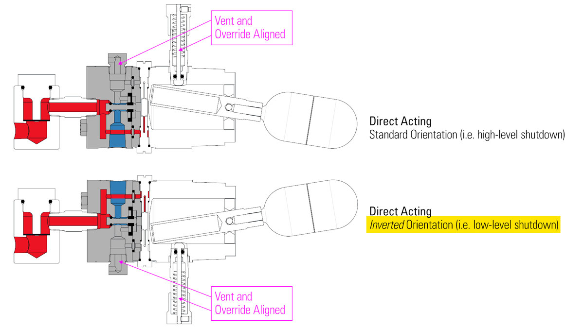
- Next, reattach the pilot housing to the body. This is where you will decide if you want direct acting or indirect acting. For direct acting, which is what we will be doing, align the vent plug on the same side as the override.
- If you are installing it for low level shutdown, you will want to install it upside down, with the button on the bottom, and keep it in direct acting mode. This will keep the test button functional and allow the switch to signal a valve only when the level gets low enough for the float to drop.
- For indirect acting, turn the pilot body so the vent plug is 180° from the override. It’s very easy to switch from direct to indirect acting on the level switches.
- Tighten the two bolts evenly with a 7/16" wrench.
Filter Body
- Apply primer and Loctite to the end of the nipple (both ends if you fully removed the nipple from the filter body).
- Install the filter and nipple onto the pilot body using a 5/8” wrench. Orient the filter body in line with the other features on the housing.
- Install the six (619) filter screens. These can all be installed at once or individually. There’s a slight rolled edge on each screen caused by the punch used to cut them. Insert these so the rolled edge is facing up and verify that the screens are resting on the inside shoulder.
- Install the (155) O-ring on the cap and add a small amount of oil.
- Install it into the filter body by hand and then fully tighten it with an adjustable wrench.