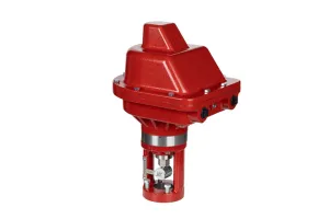
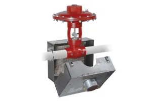

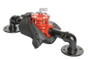

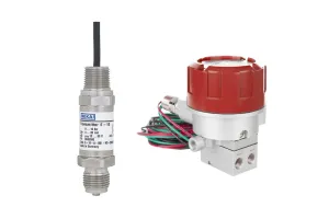
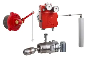
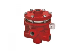
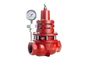
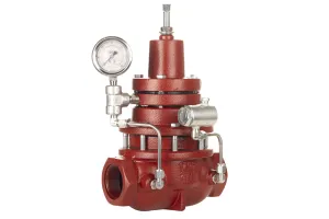
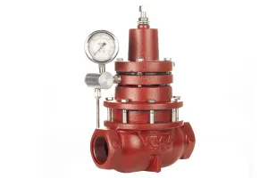
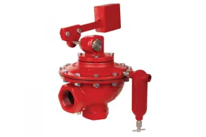
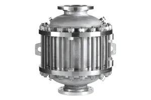
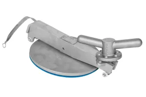
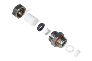
Kimray’s Back Pressure Regulator is a staple in oil and gas production and used in numerous oilfield applications. While the body and other shell components can last for years, the internal components experience wear and tear that can affect production processes.
In this video we’ll show you how to disassemble, inspect, and maintain a standard 2” Back Pressure Regulator using a Kimray Master Repair Kit.
Tools & Components Needed
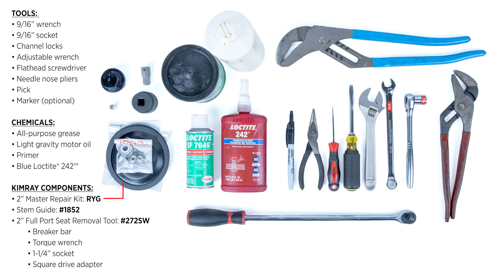
For the 2” model, you’ll need the following tools, components and chemicals:
Tools
- 9/16” wrench
- 9/16” socket
- Channel locks
- Adjustable wrench
- Flathead screwdriver
- Needle nose pliers
- Pick
- Marker (optional)
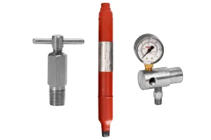
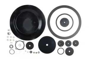
Kimray Components
- 2” Master Repair Kit: RYG
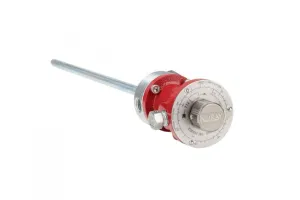
- Stem Guide: #1852
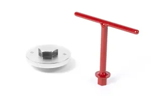
- 2” Full Port Seat Removal Tool: #272SW
- Breaker bar
- Torque wrench
- 1-1/4” socket
- Square drive adapter
Chemicals
- All-purpose grease
- Light gravity motor oil
- Primer
- Blue Loctite® 242™
| Size | Master Repair Kit | Tool | Trim Size | |
| 1/2" Trim | 1" Trim | |||
| 1" | RYD Corrosive: RYDS6 | Seat Removal Tool | N/A | |
| Stem Guide | 1851 | |||
| 1" Trim | 2" Trim | |||
| 2" | RYG Corrosive: RYGS6 | Seat Removal Tool | 4934SW | 272SW |
| Stem Guide | 1852 | |||
| 1-5/8" Trim | 3" Trim | |||
| 3" | RYK Corrosive: RYKS6 | Seat Removal Tool | Ductile: 1219SW Steel: 1219HTSW | 273SW |
| Stem Guide | 1853 | |||
| 2" Trim | 4" Trim | |||
| 4" | RYO Corrosive: RYOS6 | Seat Removal Tool | Ductile: 1220SW Steel: 1220HTSW | 274SW |
| Stem Guide | 1854 | |||
| 3" Trim | 6" Trim | |||
| 6" | RYR Corrosive RYRS6 | Seat Removal Tool | Ductile: 1221SW Steel: 1221HTSW | 275SW |
| Stem Guide | 1855 | |||
CAUTION: The procedures demonstrated in this video are intended for general informational purposes only. Always follow your company’s safety requirements, policies, and applicable regulations when performing any maintenance or repair.
Before starting any repair or maintenance activities:
Review and follow all WARNING and CAUTION notes found in the Kimray Installation, Operation, and Maintenance (IOM) guide for your specific product.
Wear all required personal protective equipment (PPE), including approved eye protection, steel toe safety shoes, and nitrile gloves to protect against exposure to chemicals and other hazardous materials.
Failure to use appropriate PPE or follow proper procedures can result in serious injury or death.
WARNING: Before any service, be certain that the valve is fully isolated and that all pressure upstream and downstream has been relieved. Use bypass valves or fully shut off the process. Be sure that any operating or instrument gas lines have been disconnected. Never assume that a check valve is fully blocking the downstream line. Never tighten any fitting or the main connections to the regulator while there is pressure on the line.
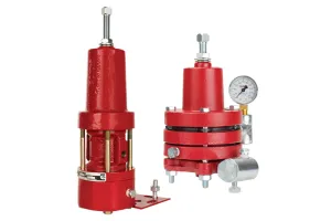
Back Pressure Regulator DISASSEMBLY:
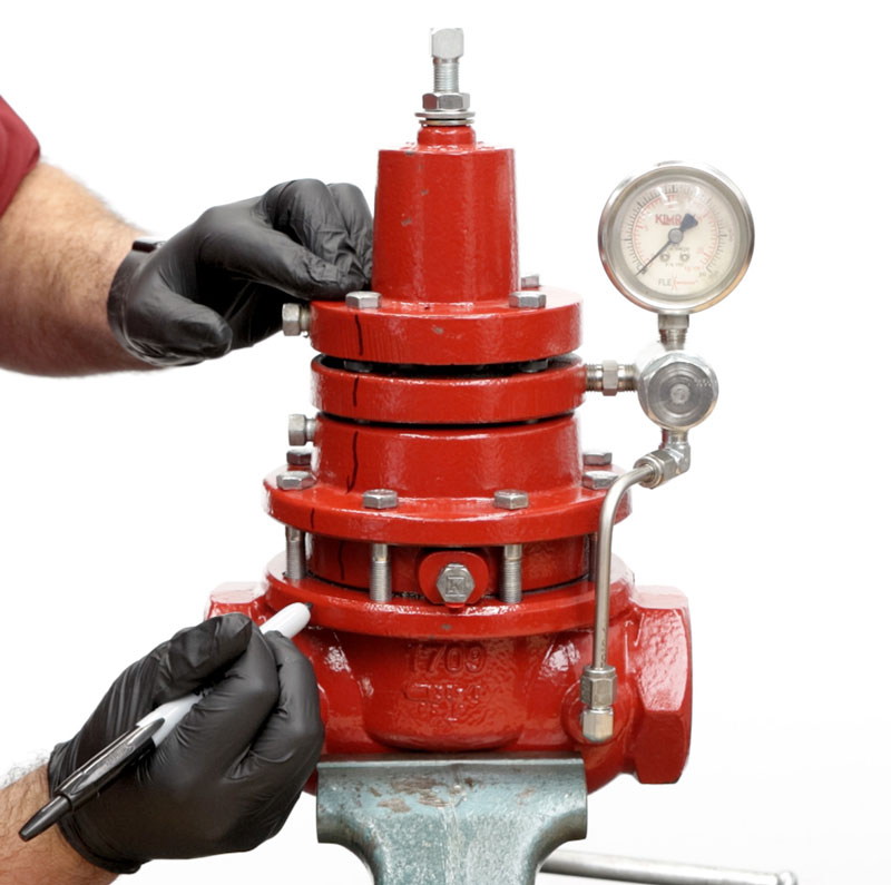
It’s helpful to make a mark down from the bonnet to the body for an easier assembly alignment.
Adjusting Screw, Tubing, Gauge, Bonnet & Spring:
- Start by using an 9/16” wrench to remove the adjusting screw.
- Discard the washer and thread seal; keep the nut.
- Use a 9/16” wrench to loosen the tubing connectors.
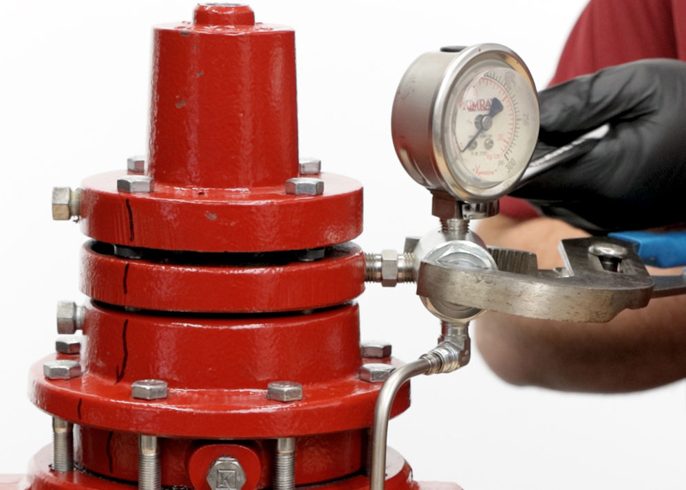
- Next, use a 9/16” wrench on the gauge. If there is a good amount of resistance, you can support the filter with channel locks to avoid breaking the nipple in the housing.
- Use a 9/16” wrench to remove the breather plugs from the bonnet, upper housing and lower housing.
- Remove the four bonnet bolts with a 9/16” wrench. Use a flathead screwdriver if needed to pry the bonnet loose.
- Remove the upper spring plate, spring and lower spring plate.
- Remove and discard the spacer ring.
- Then rotate the pilot housing to remove the tubing.
Pilot Housing
- Separate the pilot housing from the upper housing.
- Flip the housing over and use a 9/16” socket to remove and discard the pilot seat, diaphragm and pilot plug.
- Discard the spring from inside the stem of the diaphragm plate.
- Remove the sense diaphragm assembly from the other side of the housing.
- Using two channel locks, grip onto the diaphragm nut and the diaphragm plate to separate the components. If they are stuck, you can get more leverage by placing the diaphragm plate in a vise.
- Discard the diaphragm but keep the nut and plate.
Lower Seat, Upper housing
- Next, use a 9/16” socket to remove and discard the lower seat and gasket.
- Remove the upper housing bolts with a 9/16” wrench.
- Use a flathead screwdriver above the breather hole to remove the housing.
- Discard the diaphragm.
- Remove the lower housing from the body. Again, you may need to wedge a flathead screwdriver to pry them apart.
- Carefully discard the oil in the lower housing. Set it aside from now, we will disassemble it later.
Body, Removable Seat
- Remove and discard the gasket from the body. It may be stuck to the lower housing.
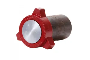
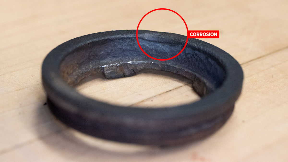
- Next, we’ll look at the removable seat. You can inspect it in place for signs of corrosion or pitting. If there’s no obvious wear and you don’t have the Kimray seat wrench, you can leave it in place. Without the correct Kimray tool to remove it, you may end up damaging the seat.
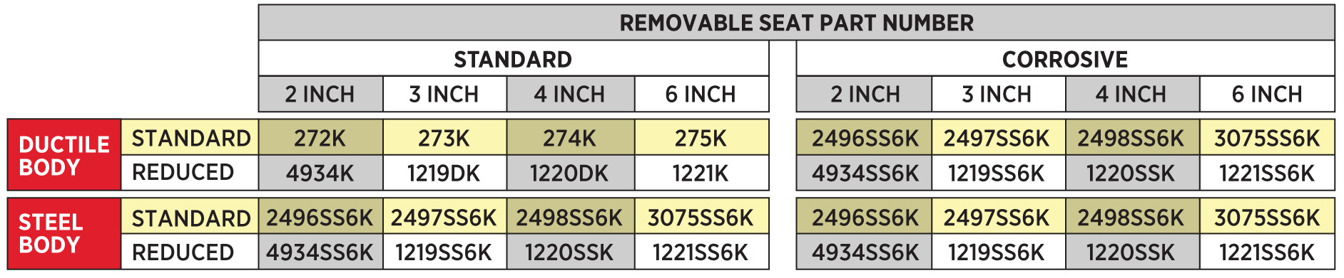
The removable seat does not come with the master repair kit. Prior to disassembly, if you suspect that the removable seat will need to be replaced, please reference the appropriate seat part number to order individually.
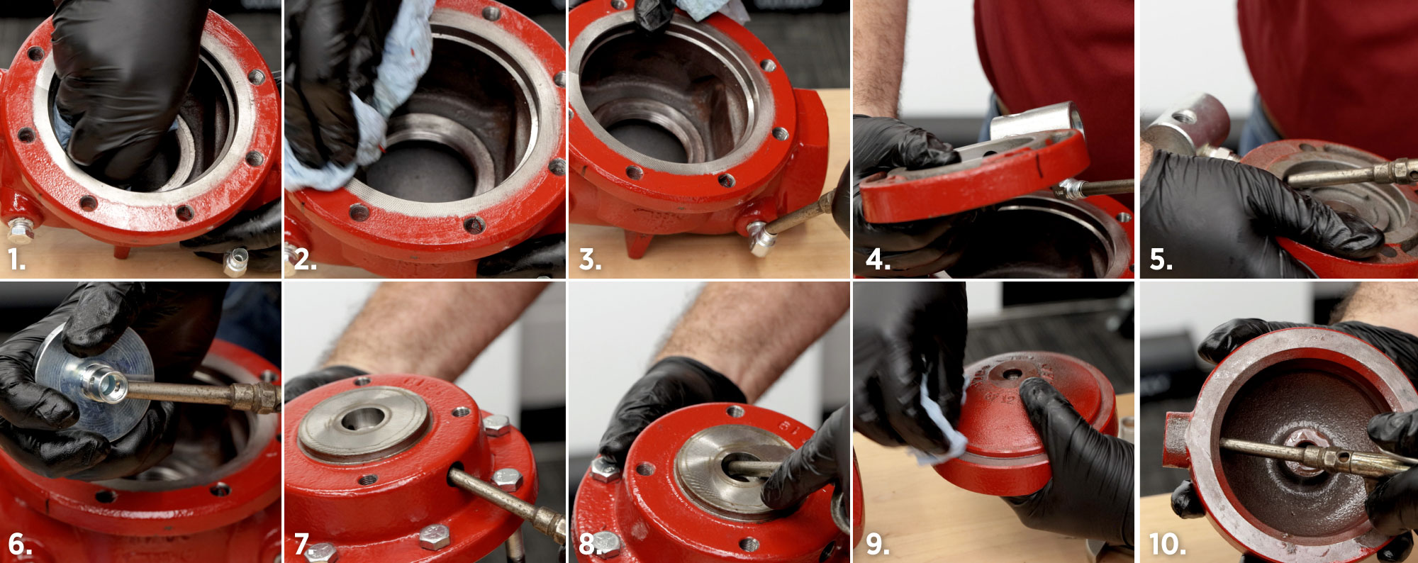
- If you have the Kimray seat tool (272SW for 2”), place it on the seat and use a 1-¼" socket and square drive adapter using a breaker bar to remove it.
- Remove and discard the gasket from the seat.
Lower Housing
- Put the lower housing into the vise by the diaphragm plate.
- With a 9/16” socket, remove and discard the nut.
- Remove the seat disc, seat and ratio plug. Use a pick or flathead screwdriver to separate. Discard the seat but keep the seat disc and ratio plug.
- Lift off the lower housing from the stem.
- Inspect the stem and diaphragm plate, but if they’re in good condition, you can leave them attached.
- Using a pick, remove and discard the O-ring and two backups from the lower housing.
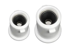
Pilot Housing, Filter
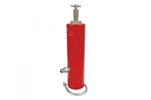
- Position the pilot housing into a vise, gripping onto the filter body. Use brass jaws to protect the filter body.
- Remove the filter cap with an adjustable wrench. Use a 1-1/8” socket if necessary.
- Discard the O-ring from the filter cap.
- Use a screwdriver and needle nose pliers to remove and discard the 6 filter screens.
Cleaning and Inspection
Clean the following parts with a wire brush and air nozzle to blow out any particles:
- Inside the valve body
- Gasket surface of the valve body
- Sense line communication port on valve body
- Filter connector
- Filter communication port
- Diaphragm plate
- Upper housing breather hole
- Upper housing communication hole
- Lower housing gasket surface
- Lower housing breather hole
Stem
- Inspect the stem for straightness, if there appears to be deflection, it will need to be replaced.
- If light scratches or galling are present, repair the stem by sanding the surface with a 220 grit or finer sandpaper. If repair is not possible, replace it.
Removable Seat
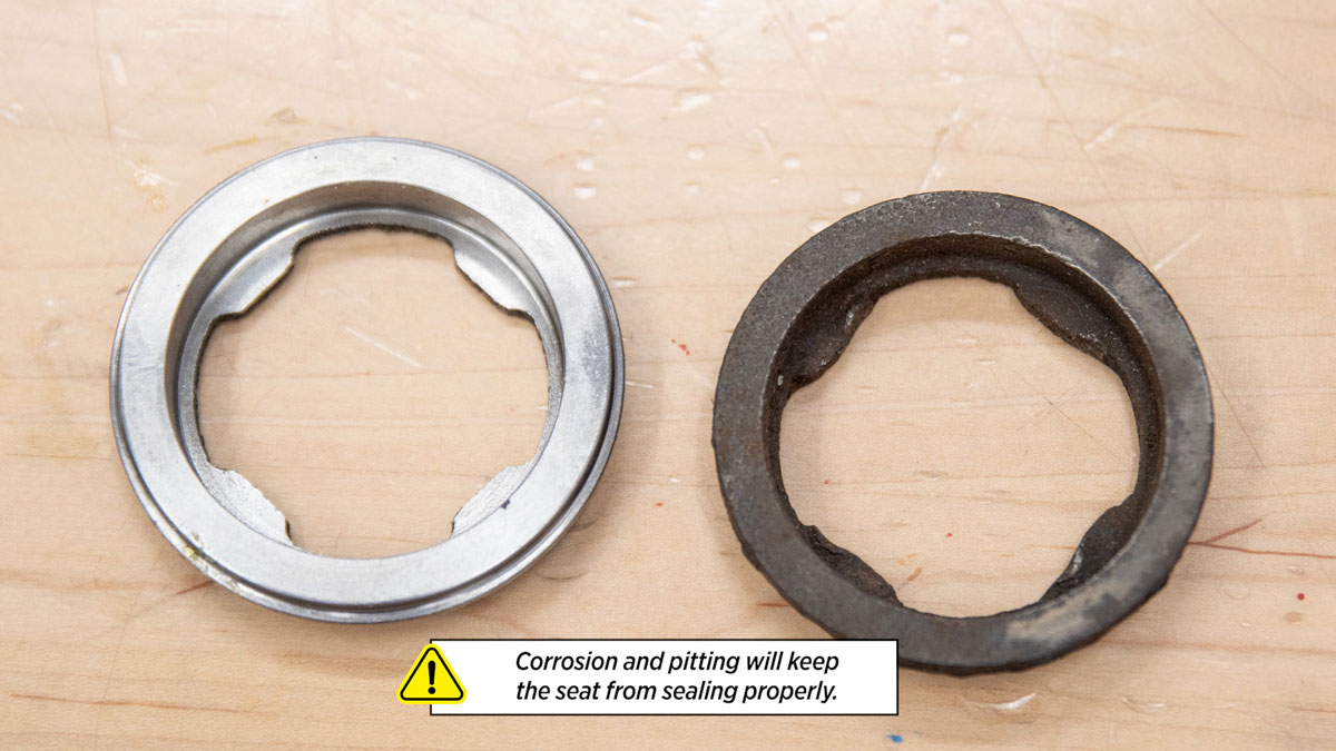
- Inspect the removable seat for damage. Corrosion and pitting will keep the elastomer seat from sealing properly. Replace it if needed.
- The removable seat does not come with the master repair kit. Prior to disassembly, if you suspect that the removable seat will need to be replaced, please reference the appropriate seat part number to order individually.
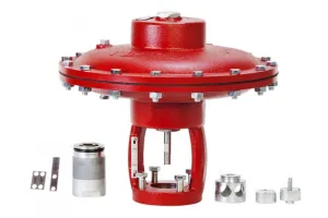
Assembly
Now we’ll begin assembly using the Kimray Repair Kit. Note that with the Master Repair Kits, you will not always use all the components included.
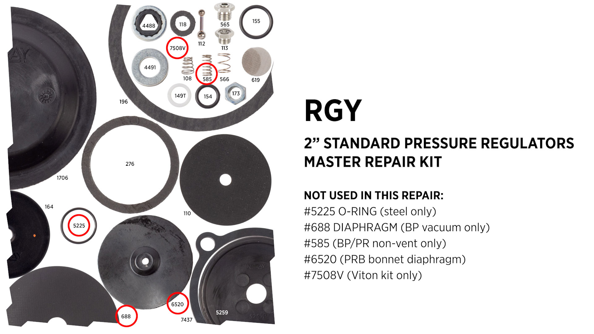
For the standard 2” back pressure regulator, you will not use the following:
- #5225 O-Ring (steel only)
- #688 Diaphragm (BP vacuum model only)
- #585 Spring (BP and PR Non-Vent models only)
- #6520 Diaphragm (PRB Bonnet Diaphragm)
- #7508V (Viton kit only)
Filter Assembly
- With the filter body in a vise, insert the six (#619) filter screens. Use a pick or small flathead screwdriver to push them into place.
- Install the (#155) O-Ring onto the filter cap.
- Lightly apply oil to the O-Ring and install the filter cap onto the filter body with an adjustable wrench.
Diaphragm Assembly
- Place the diaphragm plate into the vise, with the female threaded end facing up.
- Thread on the (#5259P) diaphragm.
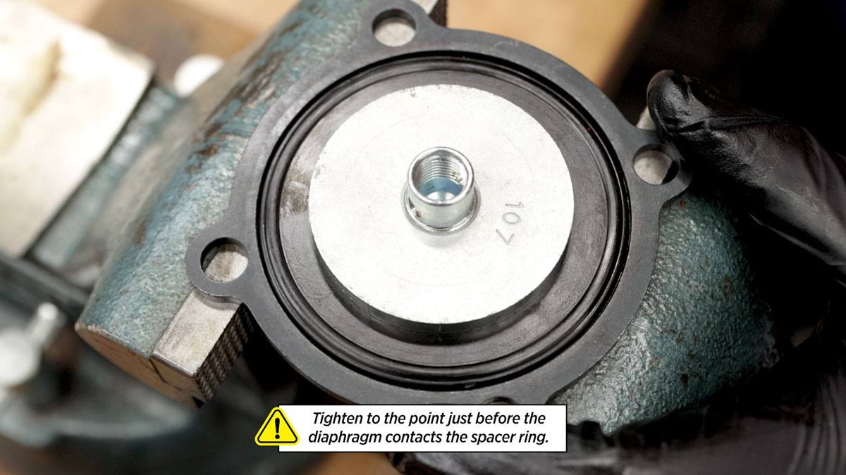
- Place the spacer ring around the diaphragm, then thread the nut onto the plate and tighten with channel locks to the point just before the diaphragm contacts the spacer ring.
- Remove the spacer ring.
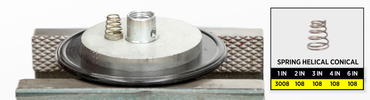
- Insert the (#108) spring into the diaphragm plate, wide end down.
Pilot Housing
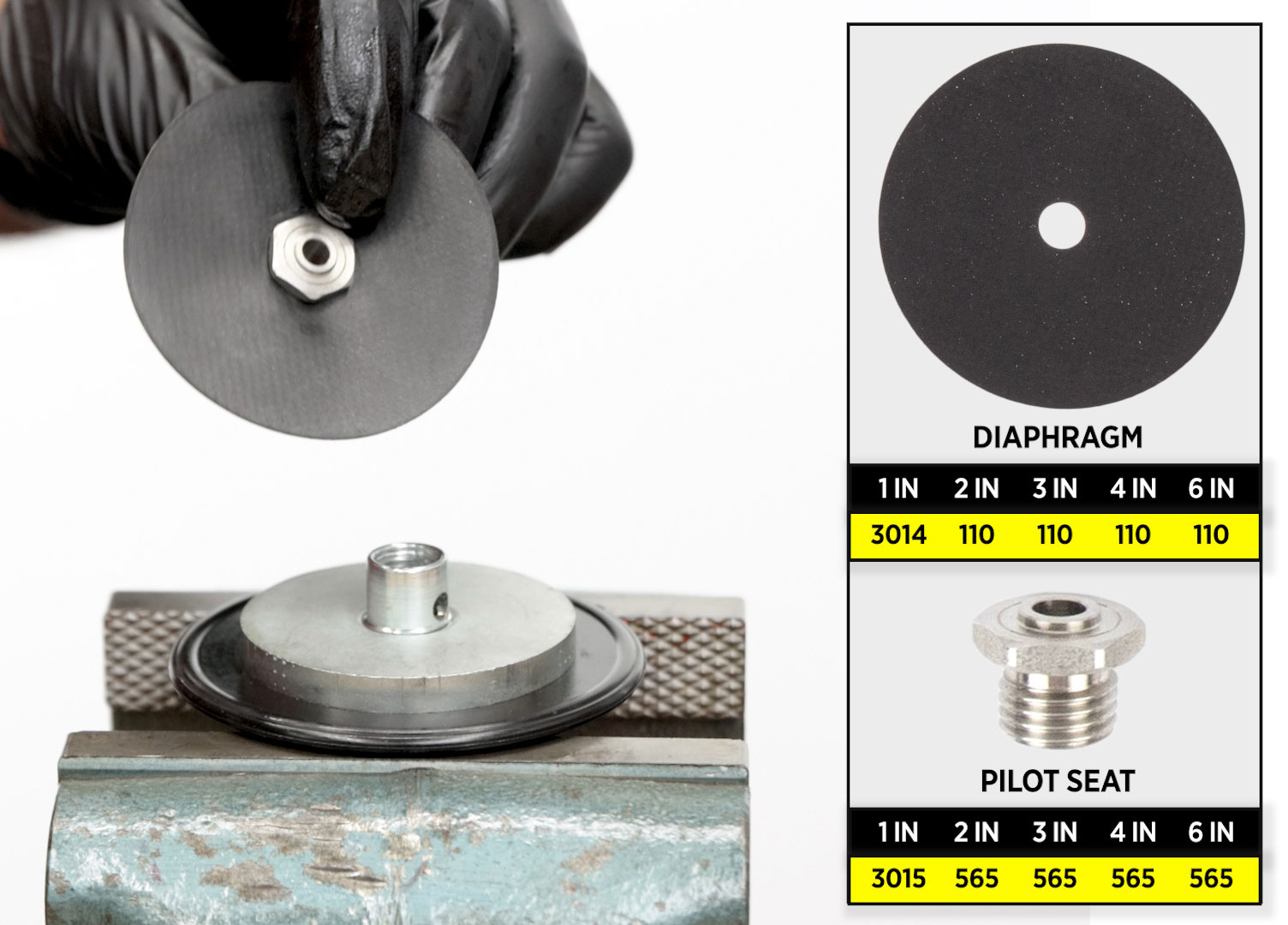
- Install the (#110) diaphragm onto the (#565) pilot seat.
- Place the (#112) pilot plug into the pilot seat, small ball first.
- Place the pilot housing assembly over the diaphragm plate assembly.
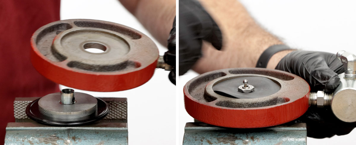
- Holding the small ball of the pilot plug, hand start the assembly into the diaphragm plate assembly.
- Fully tighten it with a 9/16” socket, but do not over tighten it. Make sure the pilot plug and pilot diaphragm are both centered.
- If you've done everything correctly, you should feel the resistance of the spring as you push the pilot plug down.
Lower Housing
- If reassembling the diaphragm plate to the stem, perform the following steps:
- Ensure brass soft jaws are in the vise
- Clamp onto stem, ensuring that the side with the shorter threads are facing up.
- Apply primer and Loctite to threads
- Hand start diaphragm plate onto stem and tighten
- Remove assembly from vise
- Remove brass soft jaws
- Place the diaphragm plate, with the stem attached, into the vise.
- Slightly stretch a (#149T) backup out like a spring. Insert one end into the lower housing and use a pick to rotate it counterclockwise until it’s fully installed.
- Next, pinch and fold the (#154) O-ring to install it into the lower housing.
- Push the O-ring and backup down to the bottom of the channel to make room for the second backup.
- Insert the second (#149T) backup into the lower housing and rotate counterclockwise as before.
- Add grease to the backups and O-ring.
- Place the Kimray stem guide onto the stem. It's best to use a Kimray stem guide to avoid shearing the O-ring when installing the lower housing over the stem.
- Add grease to the stem guide.
- Put on the lower housing, then remove the stem guide.
- Next, place the seat disc on the stem.
- Then add the new (#164) seat.
- Place the ratio plug on top.
- Apply all-purpose grease to the threads of the stem.
- Hand start the new (#173) lock nut threads before fully tightening with a 9/16” wrench to the point where the seat disc no longer rotates. Do not overtighten.
- Apply all-purpose grease to the lower housing shoulder.
- Place the (#196) gasket on top, then apply grease to the gasket.
- Remove the lower housing from the vise and make sure that the lower stem can move freely.
Removable Seat
- Place the valve body in the vise.
- Add grease to the threads of the removable seat.
- Then install the (#276) gasket onto the seat.
- Apply grease to the top of the gasket as well.
- Install the removable seat with the Kimray seat tool to 30 ft-lb. Use the torque specs for your size valve. Overtightening the seat can damage the gasket.
Lower Housing
As you assemble the valve, follow the markings you made before disassembly.
- Place the lower housing assembly into the valve body. Align the markings if you have them.
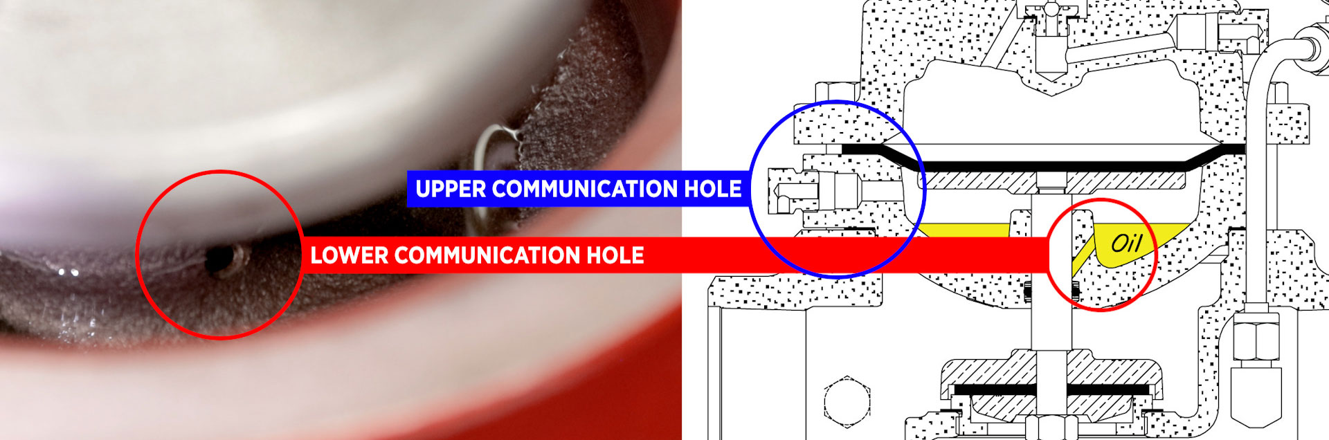
- Add any kind of light gravity all-purpose oil to the housing until the oil is above the lower communication hole and below the upper communication hole.
- Being careful not to pinch your fingers, push down the diaphragm plate directly on top.
- Install the main (#1706) diaphragm onto the lower housing assembly, beveled side down.
Upper Housing
- Install the upper housing onto the lower housing and hand-start the bolts. Again, use your markings to properly align it.
- Fully tighten in a torque star pattern.
- Next, install the (#118) gasket onto the (#113) pilot seat.
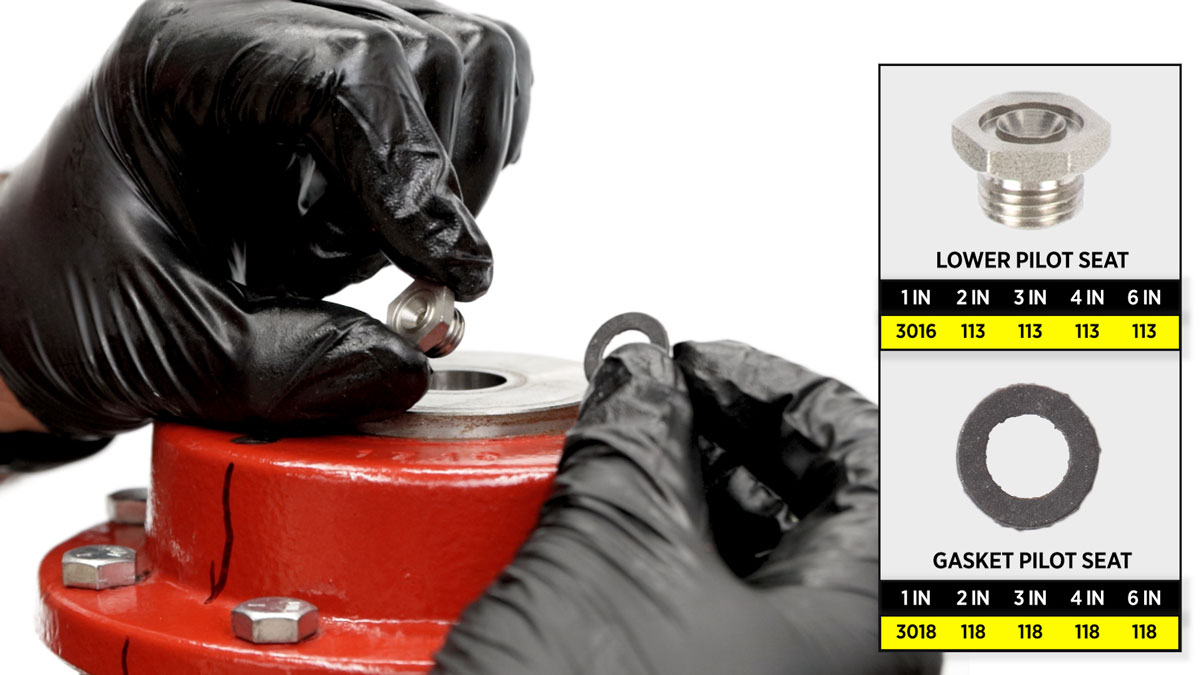
- Hand start the seat into the upper housing and fully tighten with a 9/16” socket. To avoid tearing through that gasket, do not over-tighten.
Pilot Housing, Bonnet, Tubing, Breather Plugs
- Next, mount the pilot housing assembly onto the upper housing, aligning your marks. The filter will be on the upstream side.
- Place the spacer ring around the upper diaphragm plate.
- Add grease to the upper diaphragm plate.
- Place the lower spring plate, spring, and upper spring plate on top.
- Then grease the top of the upper spring plate.
- Place the bonnet on top and hand start the bolts but do not tighten them all the way.
- Install the tubing, but do not fully tighten the tubing fittings.
- Now tighten the bonnet bolts fully with a 9/16” wrench.
- Once the bonnet bolts are tight, tighten the tubing fittings with a 9/16” wrench.
- Install all three breather plugs orienting the breather hole to point down.
Gauge
- Apply primer and Loctite to the threads on the gauge.
- Then install the gauge into the filter with a 9/16” wrench.
Adjusting Screw
- Apply grease to the first few threads of the adjusting screw.
- Put the nut, (#4491) washer, and (#4488) thread seal onto the adjusting screw.
- Tighten it into the bonnet with a 9/16” wrench.
If you have any questions about this repair, contact your local Kimray store or authorized distributor. You can also Get Product Support from our Technical Sales Support team. Get Product Support Here
