


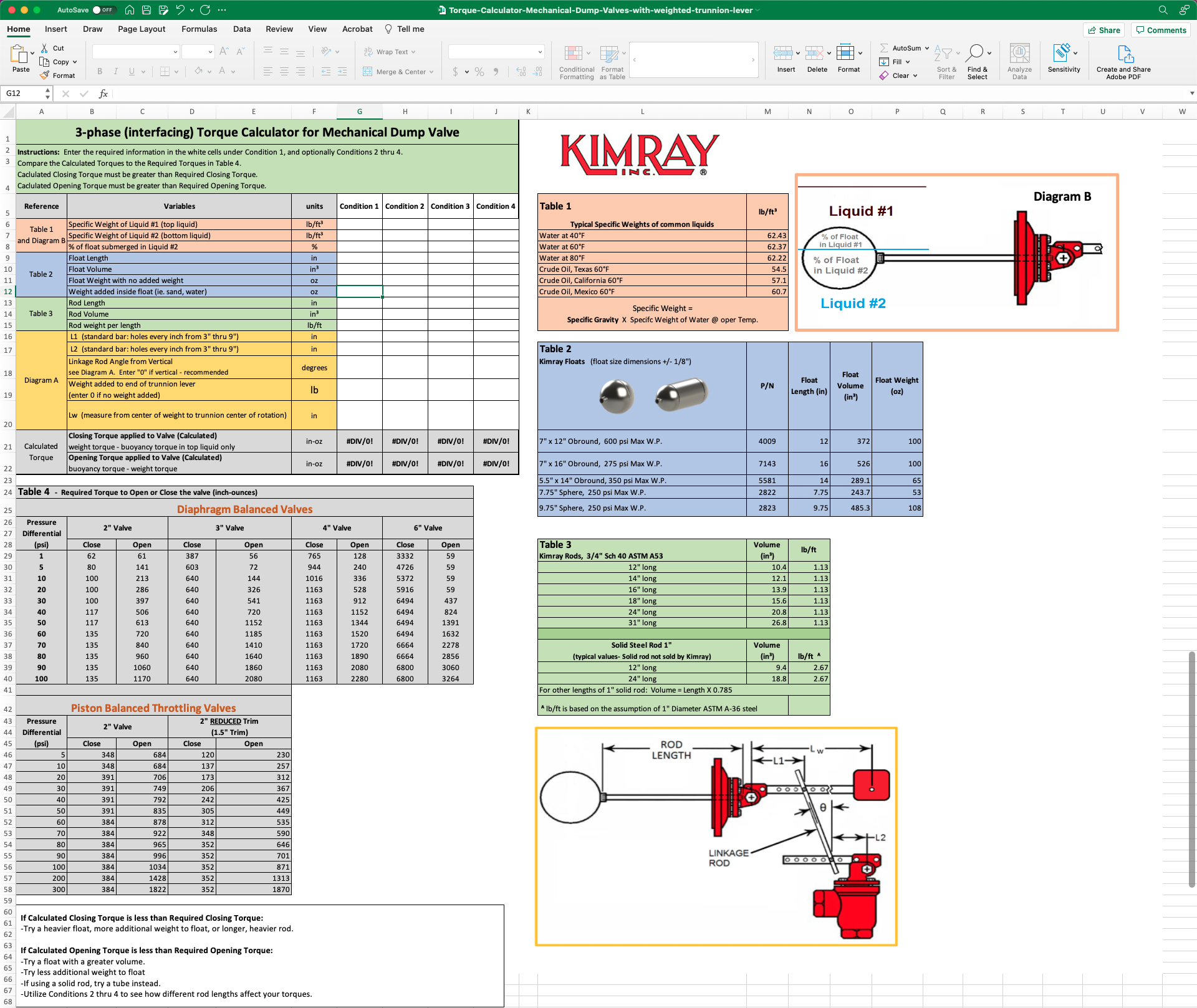
The Torque Calculator will help you determine how much opening and closing torque will be required for your lever operated dump valve in provided conditions. By changing conditions, this can help you determine if you need a larger float, a longer rod, more weight added inside the float, or a larger valve.
Download the Torque Calculator
Here's how it works for two different scenarios.
Scenario 1: size for a 2-phase separator
The torque calculator has two tabs: 2-phase and 3-phase.
You have a 2-phase oil vessel (SG=0.7), and you want to determine what size float and length of rod you will need for the trunnion assembly.
- Table 1: Determine Specific Weight of the liquids
Reference Table 1. Always multiply by the specific weight of WATER from Table 1, regardless of whether you’re calculating for oil or water.
0.7 (Specific Gravity Oil) x 62.22 (Specific Weight Water) = 43.554
- Table 2: Select a float from Table 2 and enter the info into the blue fields in Condition 1.
If you don’t know where to begin, start with a 7” x 12” Obround float.
- Table 3: Select a rod length from Table 3 and enter the info into the green fields in Condition 1.
- Diagram A: Reference the diagram and enter the info into the yellow fields in Condition 1.
These entries will depend on the location of the valve relative to the trunnion.
- Calculated Torque: See your results and compare to the data in Table 4.
Calculated Torque must be higher than the Required Torque in Table 4. If they are not, try using one or more of the tips at the bottom.
Scenario 2: size for 3-Phase, interface control
The torque calculator has two tabs: 2-phase and 3-phase.
Torque Calculator Walkthrough:
The top left condition fields are for your conditions. All other tables are for reference. You are designing a system to interface between oil (SG 0.8) and water (SG 1.1) at 80°F and you have a Kimray 7” x 16” Float and 12” Rod.
- Specific Weight of Liquid #1 (top liquid = oil)
Reference Table 1. Always multiply by the specific weight of WATER from Table 1, regardless of whether you’re calculating for oil or water.
0.8 (Specific Gravity Oil) x 62.22 (Specific Weight Water) = 49.776
- Specific Weight of Liquid #2 (bottom liquid = water)
Reference Table 1. Always multiply by the specific weight of WATER from Table 1, regardless of whether you’re calculating for oil or water.
1.1 (Specific Gravity Water) x 62.22 (Specific Weight Water) = 68.442
- Percentage of Float Submerged in Liquid #2
Diagram B illustrates the float in a liquid. If we use 50%, this means the valve will actuate when the water level is 50% of the way up the float.
- Float Length
Reference Table 2.
- Float Volume
Reference Table 2.
- Float Weight with no added weight
Reference Table 2.
Weight added inside float (i.e. sand, water, BBs)
This calculation can be trickier, since the true weight is not likely to be measured on location. Use this chart for approximations for water, sand, and BBs added to the five different floats, filled half full. If you're unsure, start with 150 oz and adjust later if needed.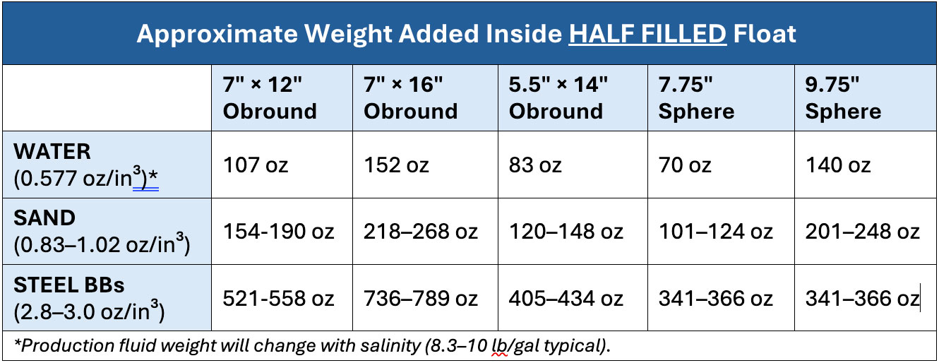
- Rod Length
Reference Table 3.
- Rod Volume
Reference Table 3.
- Rod weight per length
Reference Table 3. Note that the weight is listed as lb/ft and will need to be calculated for the various lengths.
- L1
Reference Diagram A. A good starting point is in the middle of the arm.
- L2
Reference Diagram A. A good starting point is in the middle of the arm.
- Linkage Rod Angle from Vertical
This angle can be estimated. It is recommended to be as vertical as possible, or 0°.
- Weight added to end of trunnion lever
Weight can be added to the end of the trunnion lever to compensate for changing fluid specific gravity due to the age of a well. A new setup will not likely have a weight. There are three standard weights: 7, 9, and 11 lbs.
- Lw
Lw can be left blank if not using a weight. If you are, input that number here.
STEP 1: Using the Calculated Torque
Once you have your calculated torque, Table 4 shows the required torque to open or close the valve compared to the pressure differential. The larger the dump valve, the more torque required to open and close that valve. Your calculated torque must be equal to or greater than your required torque.
If calculated CLOSING torque is less than the required closing torque:
- Adjust the linkage rod placement
- Heavier float
- Add weight to the float
- Choose a longer rod length
If calculated OPENING torque is less than the required opening torque:
- Use a float with greater volume
- Remove weight from the float
- If using a solid rod, try a tube instead
If you get a NEGATIVE TORQUE value:
- Adjust the input for weight added inside float.
- Add more torque by making L1 shorter and L2 longer. Be aware that this adjustment will result in more frequent dump cycles.
Tip: Copy data from Condition 1 to the other 3 Conditions, then make small changes and compare the different results.
STEP 2: Weighting a Float for Interface
See our video and blog about How to Weight a Float for more details about this process.
How to Weight a Float Ball for Liquid Level Control
STEP 3: Adjust the Linkage Rod
See our video and blog for more information
Oil and Water Interface: 2 Critical Adjustments for Accurate Liquid Level Control
To speak with an expert about your liquid level control set up, contact your local Kimray store or authorized distributor.