









Signals in the Oilfield & How Devices Talk to Each Other
Beyond supplying power, oilfield electrical systems also must communicate information. Sensors, controllers, and actuators constantly exchange signals that tell equipment what to measure and what to do.
 Analog Signals
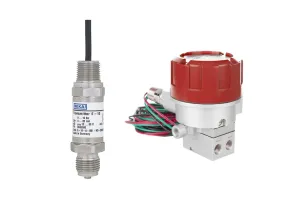
An analog signal represents a value that changes continuously over a range. Instead of just “on” or “off,” analog signals show how much of something is happening. For example, a pressure transmitter on a flowline might send a signal that represents pressure anywhere from 0 to 1,500 psi. As pressure increases or decreases, the signal changes smoothly to match it.
In oil and gas production, analog signals are commonly used for pressure, level, flow, temperature, and position. They allow operators to see trends, not just alarms. You can tell whether pressure is slowly rising, rapidly falling, or staying stable, all long before a shutdown occurs.
 Discrete Signals
A discrete signal is much simpler. It has only two states: on or off. This could also mean open/closed or energized/de-energized.
In the oilfield, discrete signals are used for valve open/closed indication, high-level or low-level switches, and emergency shutdowns.
For example, a level switch on a tank might send a discrete signal when the tank reaches a high level. It doesn’t tell you how full the tank is, only that it crossed a set point. Discrete signals are reliable, easy to troubleshoot, and critical for safety interlocks, but they don’t provide detailed process insight.
mA Signals – Why Current Is Used for Analog Data
Most analog signals in the oilfield use milliamps (mA), typically a 4–20 mA signal.
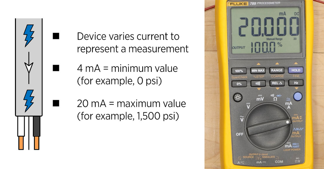
Milliamps is a unit of current. Instead of varying voltage, the device varies current to represent a measurement:
- 4 mA = minimum value (for example, 0 psi)
- 20 mA = maximum value (for example, 1,500 psi)
This approach is used because current signals are less affected by wire resistance and can run long distances without losing accuracy. In a current loop, the transmitter automatically increases voltage to maintain the required current. Only when resistance gets too high does the transmitter signal fail.
You may also be wondering why does the minimum value start at 4mA? Think of it as a built-in diagnostic. If you had a 0 mA reading, you wouldn’t know immediately if it were detecting 0 psi or if there was a problem in the system.
For example, 0 mA is likely an indication of a broken wire or failed device. A reading stuck at 4 mA is either at true zero or there is a sensor issue. An unstable reading might be a loose connection. If the output doesn’t move a valve, the supply maybe be the issue instead.
When you understand all these principles and terms together, electrical systems look less intimidating and instead become tools you can reason through and troubleshoot.
